4.5 Operating method from master device
4-17
4. Operation
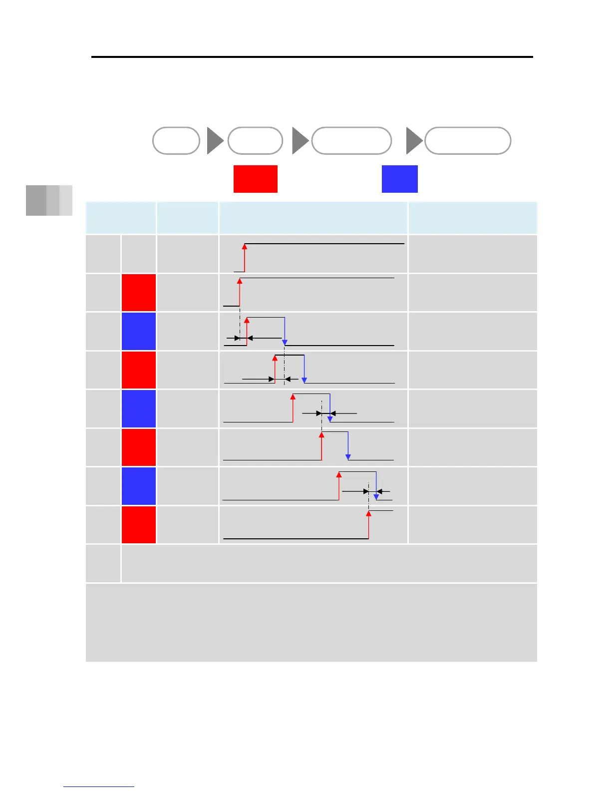
This shows the PLC timing chart for operating the ELECYLINDER.
The basic process is as follows.
[Basic timing chart]
Category
Signal
abbreviation
Timing chart Remarks
1 Power Power ON
LED status: OFF → Orange ON → Green ON
24VDC power supply is turned ON.
2 Output * ALM
Turns ON if no alarm has been
triggered.
3 Input ST0 Δt1
When the [ST0] signal is turned
ON, home return operation begins.
4 Output LS0
Δt2
Home return operation is complete
and the unit moves to the backward
end.
5 Input ST1
Δt2
Moves to the forward end.
6 Output LS1
Moved to the forward end.
7 Input ST0
Δt2
Moves to the backward end.
8 Output LS0
Moved to the backward end.
9
After this, "5" to "8" repeat.
Δt1: Wait approximately 0.5 seconds from when the *ALM signal turns ON before inputting the first command.
Δt2: The time taken for the ELECYLINDER actually to reach the forward or backward end after the LS signal turns ON.
Consider Δt2 when giving instructions for the next operation from the PLC to the ELECYLINDER.
Δt2 becomes longer for larger detection ranges.
Δt2 also changes with the size of the transported load and acceleration/deceleration speeds.
Output Input
ELECYLINDER →
output signals to PLC
PLC → input signals to
ELECYLINDER
Power ON Home return Move to forward end Move to backward end

 Loading...


