429
INTELLIGENT ACTUATOR
Appendix
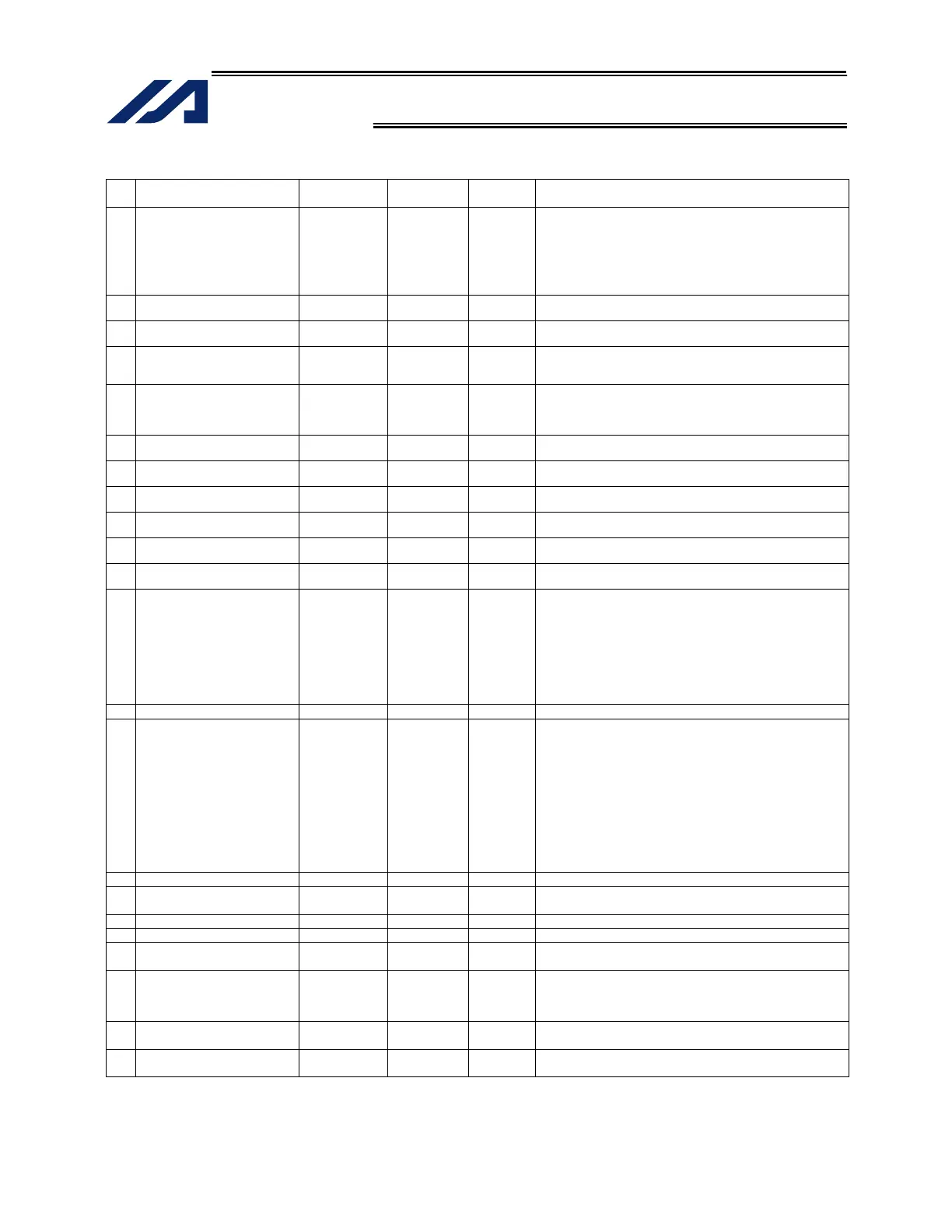
Axis-Specific Parameters
No Parameter name
Default value
(Reference)
Input range Unit Remarks
65 Mating synchro-axis number 0 0 to 8 Must be input for both axes. (Of the axis pair, the axis with
the smaller axis number becomes the master axis. Both
axes must have the same resolution characteristics.
Commands cannot be issued to the slave axis.)
* The actuators must be installed by physically aligning
the “positions at the end of home return” of the synchro
master and slave axes. (Invalid if “0” is set)
66 Mode selection for rotational
movement axis
0 0 to 5 0: Normal, 1: Index mode
67 Short-cut control selection for
rotational movement axis
0 0 to 5 0: Do not select, 1: Select (Valid only in the index mode
AND when an incremental encoder is used)
68 Mode selection for linear
movement axis
0 0 to 5 0: Normal, 1: Infinite-stroke mode (Note: Positioning
boundary applies. This setting can be specified only
when an incremental encoder is used.)
69 Torque limit upon stopping of
synchro slave axis
0 0 to 70 % Not limited, if “0.” Effective only when specified for the
synchro slave axis.
* Related information: Axis-specific parameter No. 52
(Main application version 0.59 or later)
70 For future expansion 0 Reference
only
71 For future expansion 0 Reference
only
72 DRVVR + offset 0 Reference
only
DRVVR (Change prohibited) To maintain symmetry of the positive
and negative sides.
73 DRVVR – offset 0 Reference
only
DRVVR (Change prohibited) To maintain symmetry of the positive
and negative sides.
74 For future expansion 0 Reference
only
75 For future expansion 0 Reference
only
76 Home-adjustment parameter
set selection
1 Reference
only
(Change prohibited)
0: P21 = Phase-Z evacuation distance at INC home return
P12 = Ideal phase-Z position coordinate
1: P32 is read automatically even when P33 = 0. P33 = 0
indicates “actual distance.”
P21 = Offset travel at home return
P12 = Coordinate achieved by offset travel at home return
P26 = Invalid
(To facilitate adjustment)
77 Synchro S pulse 3 0 to 99999 Pulse *Related information: Axis-specific parameter No. 52
78 Maximum takeoff command
amount
0 -3000 to
3000
0.001 mm
Maximum lift command amount before brake unlock (Input
with sign)
(Suppression of momentary drop upon servo ON when a
heavy object is placed)
* Important: Input using the same sign as the rising
coordinate direction. (0.100 mm to 0.500 mm in absolute
value as a guideline)
* The servo-ON check time (axis-specific parameter No.
30) must also be extended (approx. 1000 to 1500 msec)
to provide a sufficient time for rise-direction torque to
follow.
(Valid only when installation of brake is specified.)
79 Actual takeoff check distance 5 0 to 3000 0.001 mm Absolute value input
80 Maximum forced-feed range 0 0 to 9999 0.001 mm For reduction of settling time. (Invalid range if “0” is set)
(Approx. 1.000 mm as a guideline)
81 Minimum forced-feed range 200 0 to 9999 0.001 mm
82 Medium forced-feed range 600 0 to 9999 0.001 mm
83 Absolute synchro slave-axis
initialization cancellation
0 0 to 5 Valid only with a synchro slave axis.
84 Maximum synchronization
correction speed of synchro
slave axis
5 0 to 100 mm/sec
Maximum travel speed for synchronization position
correction of slave axis. Valid only with a synchro slave
axis.
* Note: Not limited by the safety speed.
85 Home-return acceleration/
deceleration
15 1 to 300 0.01 G
86 Zone 1 MAX 0 -99999999 to
99999999
0.001 mm Valid only when MAX > MIN. * Must be inside the range for
at least 3 msec.

 Loading...


