430
INTELLIGENT ACTUATOR
Appendix
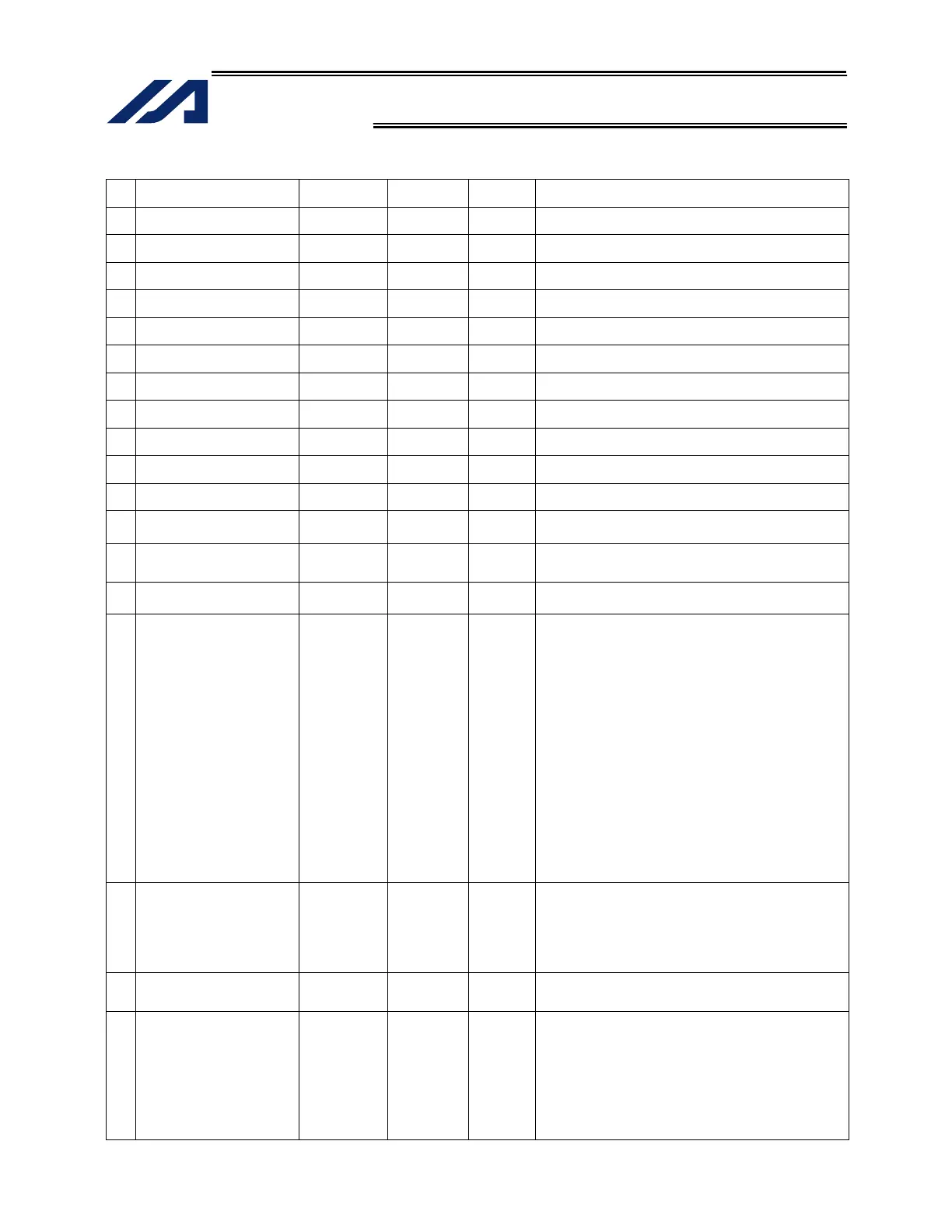
Axis-Specific Parameters
No Parameter name
Default value
(Reference)
Input range Unit Remarks
87 Zone 1 MIN 0 -99999999 to
99999999
0.001 mm Valid only when MAX > MIN. * Must be inside the range for
at least 3 msec.
88 Zone 1 output number 0 0 to 899 Physical output port or global flag (Output is invalid if “0” is
input; multiple specification is invalid)
89 Zone 2 MAX 0 -99999999 to
99999999
0.001 mm Valid only when MAX > MIN. * Must be inside the range for
at least 3 msec.
90 Zone 2 MIN 0 -99999999 to
99999999
0.001 mm Valid only when MAX > MIN. * Must be inside the range for
at least 3 msec.
91 Zone 2 output number 0 0 to 899 Physical output port or global flag (Output is invalid if “0” is
input; multiple specification is invalid)
92 Zone 3 MAX 0 -99999999 to
99999999
0.001 mm Valid only when MAX > MIN. * Must be inside the range for
at least 3 msec.
93 Zone 3 MIN 0 -99999999 to
99999999
0.001 mm Valid only when MAX > MIN. * Must be inside the range for
at least 3 msec.
94 Zone 3 output number 0 0 to 899 Physical output port or global flag (Output is invalid if “0” is
input; multiple specification is invalid)
95 Zone 4 MAX 0 -99999999 to
99999999
0.001 mm Valid only when MAX > MIN. * Must be inside the range for
at least 3 msec.
96 Zone 4 MIN 0 -99999999 to
99999999
0.001 mm Valid only when MAX > MIN. * Must be inside the range for
at least 3 msec.
97 Zone 4 output number 0 0 to 899 Physical output port or global flag (Output is invalid if “0” is
input; multiple specification is invalid)
98
to
100
(For expansion) 0 ~
101
Allowable time for exceeding
continuous-operation enable
torque
0 0 to 300 S
If 0, the allowable time for exceeding continuous-operation
enable torque is not monitored.
(Main application version 0.71 or later)
102
to
103
(For expansion) 0 ~
104 Target axis specification for
multiple-slider near-miss
detection
0H 0H to
FFFFFFFFH
Bits 0 to 3: Mating axis number of near-miss detection
target (on the positive side of the coordinate
system of the target axis)
Bits 4 to 7: Mating axis number of near-miss detection
target (on the negative side of the coordinate
system of the target axis)
* The mating axis must be entered for each
axis. (Of the pair, the axis with the smaller
axis number becomes the main axis for the
sake of convenience.)
* For each axis, only an axis whose
resolution and other related characteristics
are the same can be specified as a mating
axis.
* In the case of synchro axes, always specify
the synchro master axis. (Specification of
the synchro slave axis is prohibited.)
* Specify “0” if no adjacent slider is present
on the applicable side of the coordinate
system of the target axis.
(Main application version 0.51 or later)
105 Effective stroke of multiple
sliders
0 0 to
99999999
0.001 mm
Set the result of [Inter-slider distance at the farthest
position allowed] – [Inter-slider distance at the closest
position allowed] when both axes subject to multiple-slider
near-miss detection are inside the range of operation.
(This parameter is valid only for the master axis between
the multiple-slider axes.)
(Main application version 0.51 or later)
106
Emergency deceleration
margin upon multiple-slider
near-miss detection
5 0 to 999 0.01 G (Main application version 0.51 or later)
107 Multiple-slider setting: Bit
pattern 1
12H 0H to
FFFFFFFFH
Bits 0 to 3: Margin for multiple-slider actual position near-
miss detection (mm)
(Of the multiple sliders, only the parameter for
the master axis is valid.)
(Main application version 0.51 or later)
Bits 4 to 7: Margin for multiple-slider command position
near-miss detection (mm)
(Of the multiple sliders, only the parameter for
the master axis is valid.)
(Main application version 0.51 or later)

 Loading...


