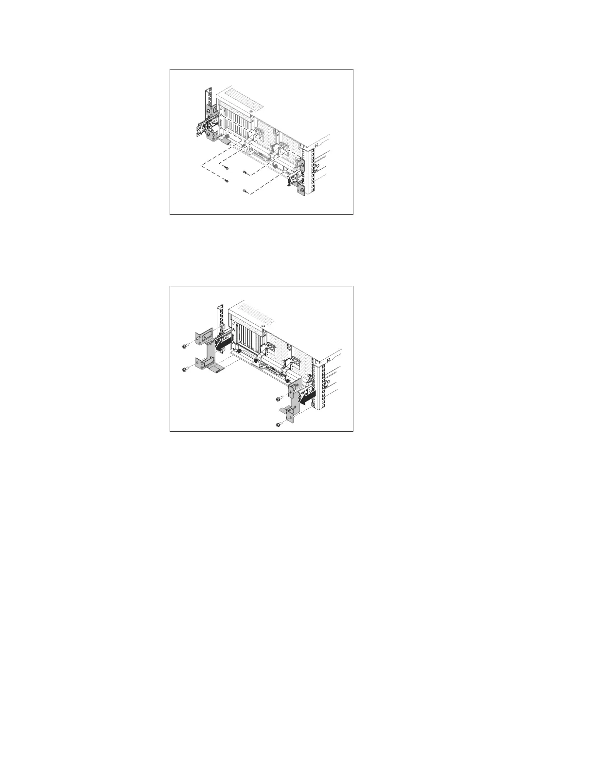
b. Remove the four M6 screws securing the shipping brackets to the frame as
shown in Figure 12.
c. Remove the shipping brackets and the cage nuts (for frames with square
mounting holes) or clip nuts (for frames with round mounting holes) from
the frame as shown in Figure 12.
d. Remove the cable tie securing the free end of the cable management arm for
Server A to the cable management support arm as shown in Figure 13 on
page 26.
ts760891
Figure 11. Removing the server retention screws
ts760896
Figure 12. Removing the bracket mounting screws and shipping brackets
Chapter 3. Installing the appliance 25