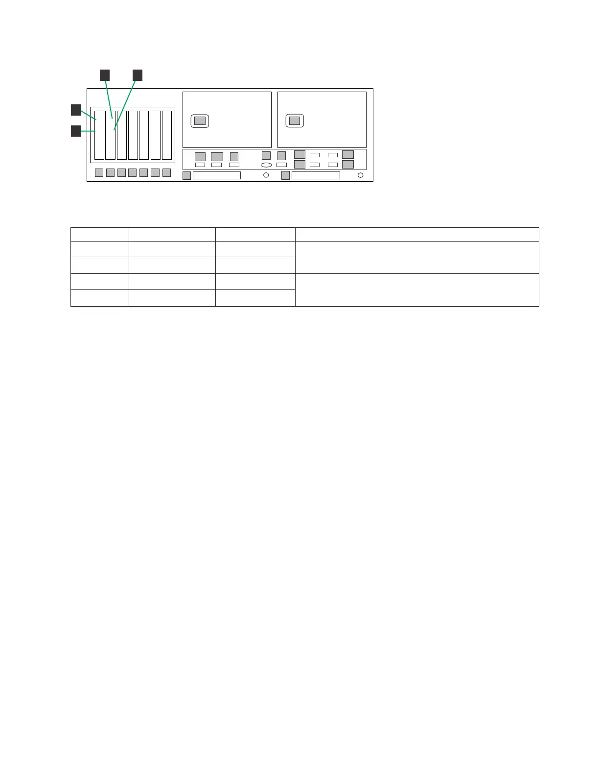
Table 17. Host Fibre Channel connections for stand-alone VTL configuration
Label From To Remarks
1 DD4A S1 1 HOST 1
v Label port 1 = Fibre Channel port 2
v Label port 2 = Fibre Channel port 3
2 DD4A S1 2 HOST 2
3 DD4A S2 1 HOST 3
v Label port 1 = Fibre Channel port 0
v Label port 2 = Fibre Channel port 1
4 DD4A S2 2 HOST 4
Procedure
Perform the following steps to make or verify Fibre Channel connections in a
stand-alone VTL appliance.
1. Connect the Fibre Channel cables to the customer host network according to
Table 17.
Note: The customer must use an additional connectivity device between the
optical Fibre directly connected to RMSS optical adapters (for example, Fibre,
ESCON, or FICON) and an external public network. It can be a patch panel,
router, switch, or other suitable device. Optical Fibre connectivity that does not
go over a public network does not require an additional connectivity device.
2. Use the applicable illustration to verify the Fibre Channel connections made in
manufacturing.
3. Ensure that all cables are routed through the cable management arms and
secured with straps. Then go to “Powering up the components” on page 68.
Fibre Channel connections in a stand-alone OpenStorage
configuration
This topic describes the configuration of Fibre Channel connections between the
disk controller and the ProtecTIER server for stand-alone OpenStorage two-drawer,
four-drawer, and eight-drawer configurations.
About this task
Note: The following figures show Fibre Channel connections in a VTL installation;
however, the relevant Fibre Channel connections to be made or verified in this
procedure are identical for OpenStorage installations.
ts760928
ProtecTIER Server A
1
1
22
1
2
3
4
5
6
7
E1
E2
1
3
2
4
P1
P2
8
A1
A2
9
B
V
E3
E4
S
1
2
1
2
3
4
2
1
Figure 24. Host Fibre Channel connections for stand-alone VTL
Chapter 3. Installing the appliance 41