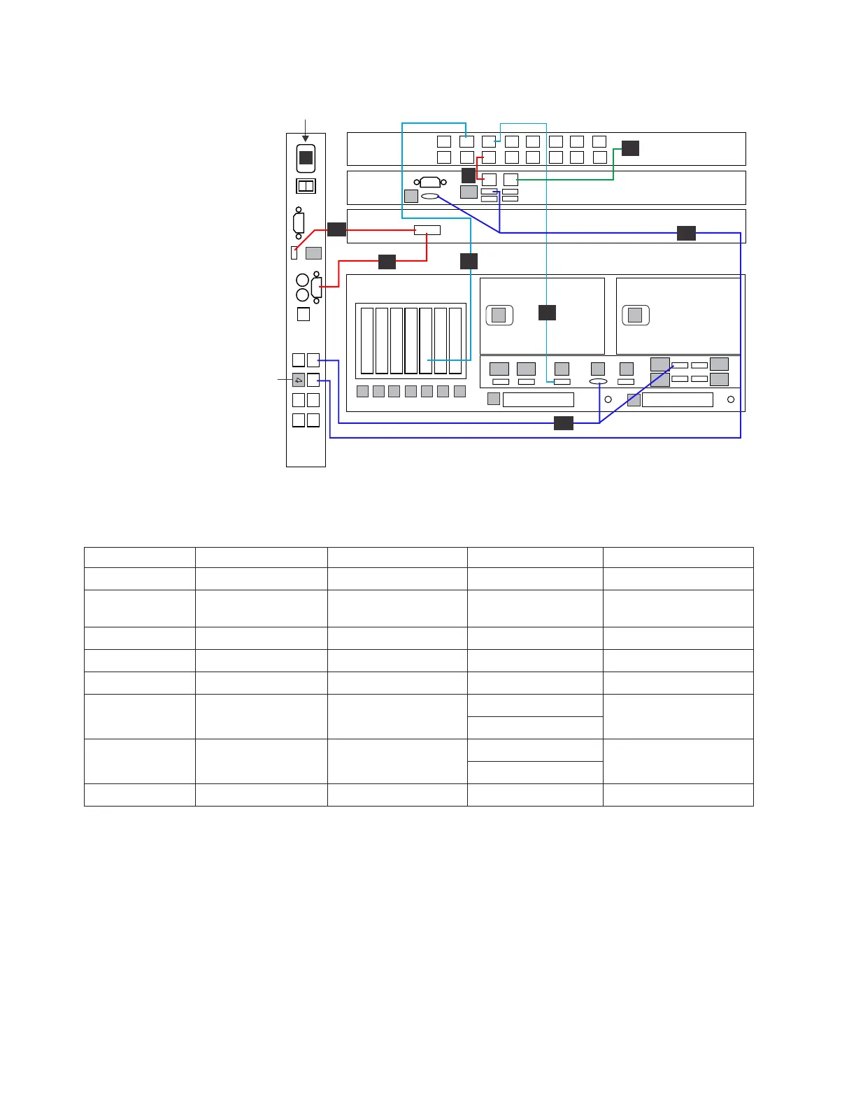
Table 11. KVM switch, TSSC, and customer network Ethernet cabling (VTL and OpenStorage configurations)
Callout From On Device To On Device/Location
9 Port 5 TSSC Ethernet switch Port 1 TSSC
10 Port 2 TSSC Customer local area
network
Customer specified
device
11 Port 4 TSSC Ethernet switch Port 4, slot 5 Server A
13 Port 6 TSSC Ethernet switch Port B (IMM) Server A
21 Video port KVM Switch Video port SC KVM
22 Port 3 KVM Switch Video port, SC Server
Port U3
23 Port 1 KVM Switch Video port, Server A
Port E1
24 Port U1 KVM Switch Video Port SC KVM
Procedure
Perform the following steps to make or verify Ethernet connections for the KVM
switch, TSSC, and customer network in a stand-alone appliance.
1. Use either Figure 15 on page 31 or Figure 16 and Table 11 to verify the cable
connections made in manufacturing.
2. If the customer requests, make the connection from the TSSC to the customer
specified device as shown.
3. Make any necessary adjustments to cable placement or labeling, and then go on
to “Replication and OpenStorage customer host network (Feature Code 3456)
connections” on page 33.
1
2
1
2
3
4
5
6
7
8
9
10
13
12
11
14
15
16
U1
8
9
A1 A2 B V S
E1
E2
E3
E4
V
U3
23
21
24
9
11
10
22
13
KVM
switch
1
2
3
4
5
6
7
8
Terminator
P
SC SW
SC Server
SC KVM
1
2
1
2
1
2
1
2
ProtecTIER Server A
1
2
34567
1
2
3
4
PP
Customer
Network
ts760988
Figure 16. KVM switch, TSSC, and customer network Ethernet cabling (VTL and
OpenStorage configurations, TSSC variant 2)
32 IBM System Storage TS7650 ProtecTIER Deduplication Appliance: Installation Roadmap Guide