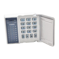
5. To toggle a selected feature ON or OFF, press the corresponding LED zone number followed by
the [*] key.
6. Once a complete selection of features has been configured, press the [#] key to exit.
When programming a location/sub-location with a bitmap, any attempt to enter invalid data will result in
an error beep (3 short beeps).
The LED zone number will not change its state.
EXAMPLE:
Location 16 allows the installer to enable up to twelve trouble conditions that may be displayed. Refer to
Table 10 for default enabled trouble conditions.
Upon entering program mode and viewing the contents of location 16, it will be noted that the enabled
trouble condition LEDs will be on.
To enable the Communications Fail Trouble Display (indicated by zone 2 LED) press the [2] key followed
by the [*] star key. A long beep will indicate a valid entry and the zone 2 LED will turn on indicating that
Communications Fail Trouble Display has been enabled.
Continue selection (or de-selection) of the desired trouble conditions. Once a final selection has been
made, press the [#] key to exit the location. The AWAY LED will turn off and a long beep will indicate the
return to location entry mode.
9. Programming Location Summary
A detailed description of each location and its options follow.
This location allows you to default the panel, user codes and their properties, and bus-wired
peripherals. Refer to Table 4 for the values, that can be programmed, and their actions.
[INSTALLER CODE] [*] [0] [*] [VALUE] [*]
Table 4: Defaulting Data
Remove Missing Devices.
Any missing devices (keypads, for example), will have its address freed up, making its address
available for a new device when it is enrolled. This MUST be performed when replacing a faulty
device. (You must wait for 10 seconds.)

 Loading...


