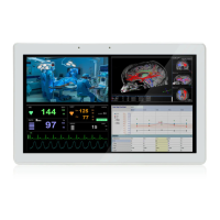
POC-W24C-ULT3 FHD Medical Panel PC
Page x
List of Figures
Figure 1-1: POC-W24C-ULT3 FHD Medical Panel PC..................................................................2
Figure 1-2: Front View....................................................................................................................4
Figure 1-3: Backlit Touch Buttons................................................................................................5
Figure 1-4: Left View.......................................................................................................................6
Figure 1-5: Bottom Panel...............................................................................................................7
Figure 1-6: Rear View.....................................................................................................................8
Figure 1-7: Dimensions (mm)......................................................................................................12
Figure 3-1: Back Cover Retention Screws.................................................................................21
Figure 3-2: HDD Bracket Retention Screws...............................................................................22
Figure 3-3: HDD Installation ........................................................................................................23
Figure 3-4: Handset Holder Retention Screws ..........................................................................24
Figure 3-5: Handset Installation..................................................................................................24
Figure 3-6: Handset Driver Folder...............................................................................................25
Figure 3-7: Handset Driver Installation.......................................................................................26
Figure 3-8: Allow API Access......................................................................................................26
Figure 3-9: Manage Program Access to Skype .........................................................................27
Figure 3-10: Handle Installation ..................................................................................................29
Figure 3-11: Insert Barcode Reader Set.....................................................................................30
Figure 3-12: Install and Connect Barcode Reader Set..............................................................30
Figure 3-13: Barcode Reader Button..........................................................................................31
Figure 3-14: Reading Light ..........................................................................................................31
Figure 3-15: 3-in-1 Combo Reader..............................................................................................32
Figure 3-16: USB Ports on the Left Panel ..................................................................................32
Figure 3-17: Combo Reader Installation ....................................................................................33
Figure 3-18: RFID Program Location..........................................................................................34
Figure 3-19: IRFR-100 Icon ..........................................................................................................34
Figure 3-20: IRFR Screen.............................................................................................................34
Figure 3-21: IRFR – Find Tags.....................................................................................................35
Figure 3-22: IRFR – UIDs..............................................................................................................35
Figure 3-23: AT/ATX Switch Location.........................................................................................37
Figure 3-24: Wall-mounting Bracket...........................................................................................38

 Loading...