HD2 Series Inverter Basic Operation Guidelines
-93-
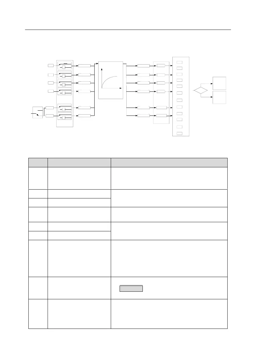
be set to act as high-speed pulse input terminal or common digital input terminal; if it is set to act as
high-speed pulse input terminal, you can also set HDIA or HDIB high-speed pulse input to serve as
the frequency reference and encoder signal input.
S1
S2
S3
S4
HDIA
HD1B
P05.08 (input terminal polarity)
P05.01
P05.02
P05.03
P05.04
T delay
T delay
T delay
T delay
T delay
T delay
P05.13
P05.15
P05.17
P05.19
P05.21
P05.23
0
1
2
3
4
5
.
.
.
.
29
30
P05.09 (digital filter time)
(Default value is 1)
(Default value is 4)
(Default value is 7)
(Default value is 0)
(Default value is 0)
(Default value is 0)
P05.00
(HDI input type)
0
1
0
1
-1
0
1
-1
0
1
-1
0
1
-1
0
1
-1
0
1
-1
P17.12
Digital input
terminal state
P07.39
Input terminal
state of present
fault
Fault?
Fault
Run
Digital function selection
T delay
T delay
T delay
T delay
T delay
T delay
P05.12
P05.14
P05.16
P05.18
P05.20
P05.22
P05.05
P05.06
The parameters are used to set the corresponding function of digital multi-function input terminals.
Note: Two different multi-function input terminals cannot be set to the same function.
The inverter does not act even if there is signal input; you
can set the unused terminals to "no function" to avoid
misacts.
Control the forward/reverse running of the inverter by
external terminals.
Set the inverter running mode to 3-wire control mode by
this terminal. See P05.13 for details.
Frequency when jogging, see P08.06, P08.07 and
P08.08 for jogging acceleration/deceleration time.
The inverter blocks output, and the stop process of motor
is uncontrolled by the inverter. This mode is applied in
cases of large-inertia load and free stop time; its
definition is the same with P01.08, and it is mainly used
in remote control.
External fault reset function; its function is the same with
the STOP/RST key on the keypad. This function can be
used in remote fault reset.
The inverter decelerates to stop, however, all the running
parameters are in memory state, such as PLC
parameter, wobbling frequency, and PID parameter.
After this signal disappears, the inverter will revert to the