HD2 Series Inverter Basic Operation Guidelines
-35-
HD2
16:02:35
Fwd
Local Ready
Set Freq
P17.00 Hz
50.00
DC Bus Volt
P17.11 V
540.0
0x0000
AboutParameter
Menu
HDIB/A/S4/3/2/1
P17.12
A B C
D
E
F
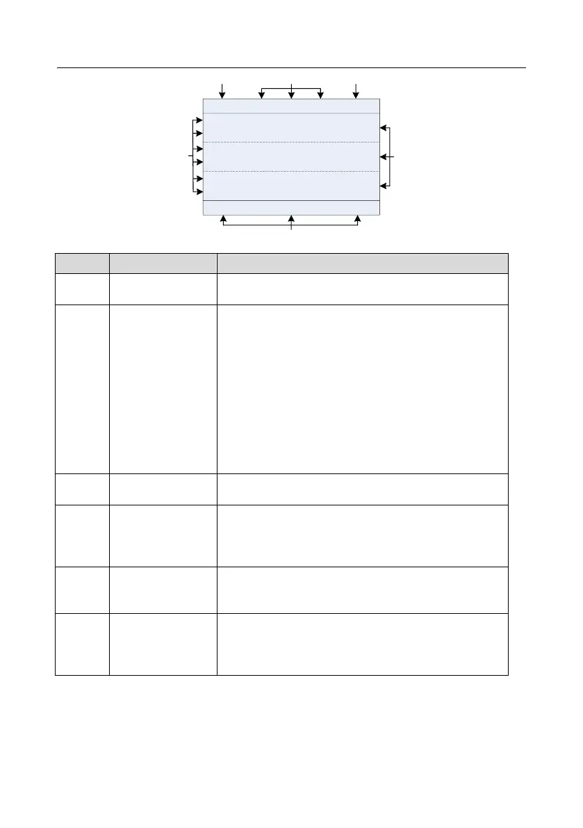
Figure 5-45-55-6 Main interface of LCD
Display the real-time; clock battery is not included; the time
needs to be reset when powering on the inverter
Inverter running state
display area
Display the running state of the inverter:
1. Display motor rotating direction: "Forward" – Run
forward during operation; Reverse – Run reversely during
operation; "Forbid" – Reverse running is forbidden.
2. Display inverter running command channel: "Local" –
Keypad; "Terminal" – Terminal; "Remote" - Communication
3. Display current running state of the inverter: "Ready" –
The inverter is in stop state (no fault); "Run" – The inverter is
in running state; "Jog" – The inverter is in jogging state;
"Pre-alarm" – the inverter is under pre-alarm state during
running; "Fault" – inverter fault occurred.
inverter model
display area
Inverter model display: "HD2" – current inverter is HD2 series
inverter
Parameter names
and function codes
on the inverter
homepage
Display a maximum of three parameter names and function
codes on the homepage. The parameters diplayed on the
homepage can be managed.
Values of parameters
on the inverter
homepage
Display the values of parameters on the inverter homepage,
which are updated in real time.
Corresponding
menus of function
keys (4), (5) and (6)
Indicate the menus corresponding to function keys (4), (5)
and (6). The corresponding menus of function keys (4), (5)
and (6) vary with interfaces, and the content displayed in this
area varies also.
5.3 Keypad display
The inverter keypad can display the stopped-state parameters, running-state parameters, function
parameter editing status, and fault alarm status.
5.3.1 Displaying stopped-state parameters
When the inverter is in stopped state, the keypad displays stopped-state parameters, and this