HD2 Series Inverter Installation Guidelines
-21-
4.3 Standard wiring of main circuit
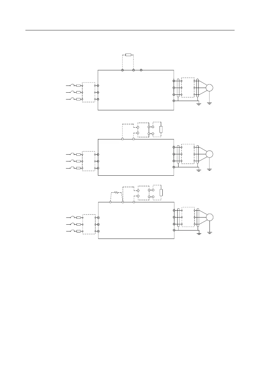
4.3.1 Wiring diagram of main circuit for a single inverter
Figure 4-7 Main circuit wiring diagram for AC 3PH 380V (-15%)–440V (+10%)
Note:
⚫ The fuse, DC reactor, braking unit, braking resistor, input reactor, input filter, output reactor and
output filter are optional parts. See Appendix D Optional Peripheral Accessories.
⚫ P1 and (+) have been short connected by default for the 380V 132kW and higher inverter models.
If you need to connect to an external DC reactor, take off the short-contact tag of P1 and (+).
⚫ When connecting the braking resistor, take off the yellow warning sign marked with PB, (+) and (-)
on the terminal block before connecting the braking resistor wire; otherwise, poor contact may
occur.
⚫ Built-in braking unit is optional for the 380V 45kW–110kW inverter models.