HD2 Series Inverter Installation Guidelines
-22-
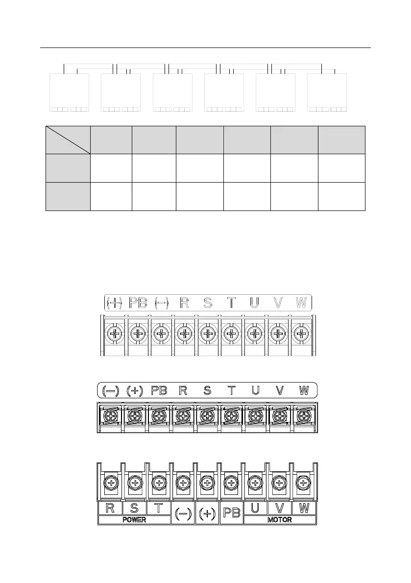
4.3.2 Wiring diagram of main circuit for parallel inverters
R S T U V W
Master
(+)
(-)
R S T U V W
R S T U V W R S T U V W R S T U V W R S T
U V W
(+)
(-)
(+)
(-)
Slave 1 Slave 2 Slave 3 Slave 4 Slave 5
(+)
(-)
(+)
(-)
(+)
(-)
Input Output
Input OutputInput OutputInput OutputInput OutputInput Output
Note:
⚫ The number of inverters that can be paralleled depends on the actual power. A maximum of six
inverters can be paralleled together.
⚫ Both the input side and output side of the master and slave need to be connected with parallel
connection cables of the same length.
4.3.3 Main circuit terminal diagram
Figure 4-8 3PH 380V 22kW and lower
Figure 4-9 3PH 380V 30–37kW
Figure 4-10 3PH 380V 45–110kW (Enabling PB when a braking unit is embedded)