HD2 Series Inverter Basic Operation Guidelines
-88-
Corresponding setting of
upper limit frequency of
HDIB
HDIB frequency input filter
time
0–1
0: Voltage type
1: Current type
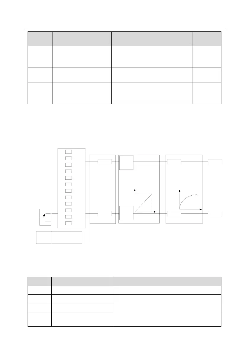
5.5.10 Analog output
The inverter carries one analog output terminal (0–10V/0–20mA) and one high-speed pulse output
terminal. Analog output signals can be filtered separately, and the proportional relation can be
adjusted by setting the max. value, min. value, and the percentage of their corresponding output.
Analog output signal can output motor speed, output frequency, output current, motor torque and
motor power at a certain proportion.
0
1
2
3
.
.
.
.
.
.
19
20
P06.14
P06.16
AO1
HDO
P06.17
P06.18
P06.19
P06.20
P06.27
P06.28
P06.29
P06.30
P06.21
P06.31
(Default value is 0)
(Default value is 0)
P06.00
(HDO output type)
0
1
P06.00
0: Open collector high-speed
pulse output
1: Open-collector output
Analog output curve setting
Analog output selection Analog output filter
AO output relationship description:
(The min. value and max. value of the output correspond to 0% and 100.00% of the pulse or analog
default output. The actual output voltage or pulse frequency corresponds to the actual percentage,
which can be through function codes.)
0–Synchronous speed corresponding to max. output
frequency