HD2 Series Inverter Basic Operation Guidelines
-32-
5 Basic Operation Guidelines
5.1 What this chapter contains
This chapter tells you how to use the inverter keypad and the commissioning procedures for common
functions of the inverter.
5.2 Keypad introduction
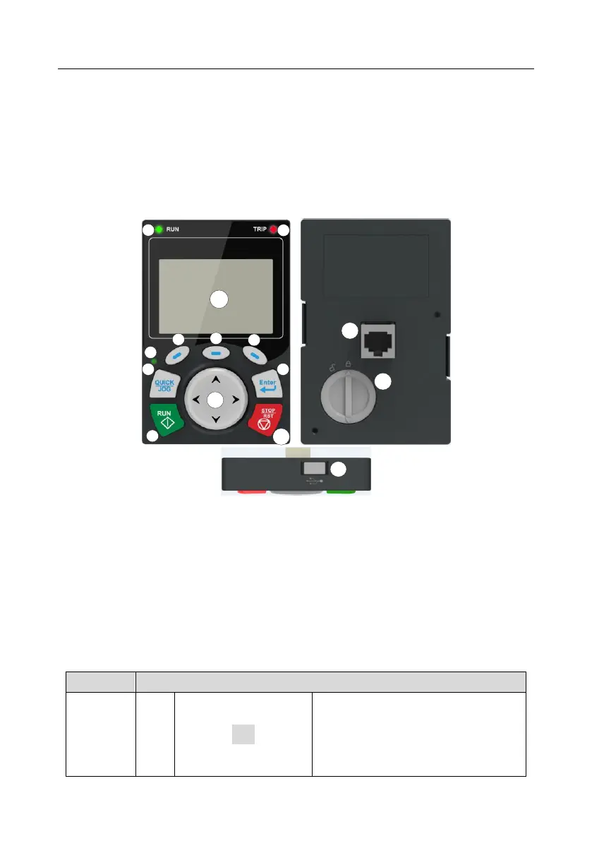
The inverter has been equipped with an LCD keypad as a standard configuration part. You can use
the keypad to control the start and stop, read status data, and set parameters of the inverter.
Figure 5-15-25-3 Keypad diagram
Note:
⚫ The LCD keypad is equipped with a real-time clock, which can run properly after being installed
with batteries even if the power line is disconnected. The clock battery (type: CR2032) is user
purchased.
⚫ The LCD keypad has the parameter copying function.
⚫ If you need install the keypad externally (that is, on another position rather than on the inverter),
you can use M3 screws to fix the keypad, or you can use the keypad installation bracket to
install the keypad. When installing the keypad externally, use an extension cable with a standard
RJ45 crystal head for connection.
Running indicator.
LED off – the inverter is stopped.
LED blinking – the inverter is in parameter
autotune
LED on – the inverter is running