HD2 Series Inverter Installation Guidelines
-29-
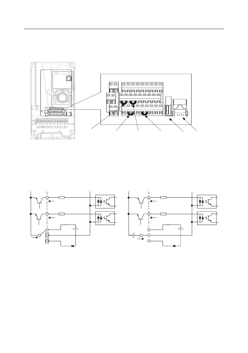
4.4.3 Input/output signal connection diagram
Set NPN /PNP mode and internal/external power via U-type short-contact tag. NPN internal mode is
adopted by default.
U-type short-
contact tag of H2
and +24V
U-type short-contact
tag of COM and CME
U-type short-
contact tag of
+24V and PW
U-type short-
contact tag of H1
and +24V
+24V
485++24V CME 485-485GCOMCOMPE H2
R01CR02C
H1 +24V
R01BR02B
PW COM HDO Y1 AO1 GND
S1 S2 S3 S4 HDIA HDIB AI1 AI2 +10V
R01AR02A
USB port
Keypad port
Figure 4-16 Position of U-type short-contact tag
Note: As shown in Figure 4-16, the USB port can be used to upgrade the software, and the keypad
port can be used to connect an external keypad. The external keypad cannot be used when the local
inverter keypad is used.
If input signal comes from NPN transistors, set the U-type short-contact tag between +24V and PW
based on the power used according to the figure below.
S1
S2
COM
PW
+ 24V
COM
+ 24V
Internal power(NPN mode)
S1
S2
COM
PW
+ 24V
COM
+24V
External power(NPN mode)
+ 24V
Figure 4-17 NPN mode
If input signal comes from PNP transistor, set the U-type short-contact tag based on the power used
according to the figure below.