HD2 Series Inverter Basic Operation Guidelines
-37-
HD2
16:02:35
Fwd
Local Run
DC Bus Volt
Back
Home
0.0 2000.0
HD2
16:02:35
Fwd
Local Run
DC Bus Volt
P17.11 V
540.00
Outp Volt
P17.03
0x0000
0x0000
AboutParameter
Menu
Outp Cur
P17.04
540.00
V
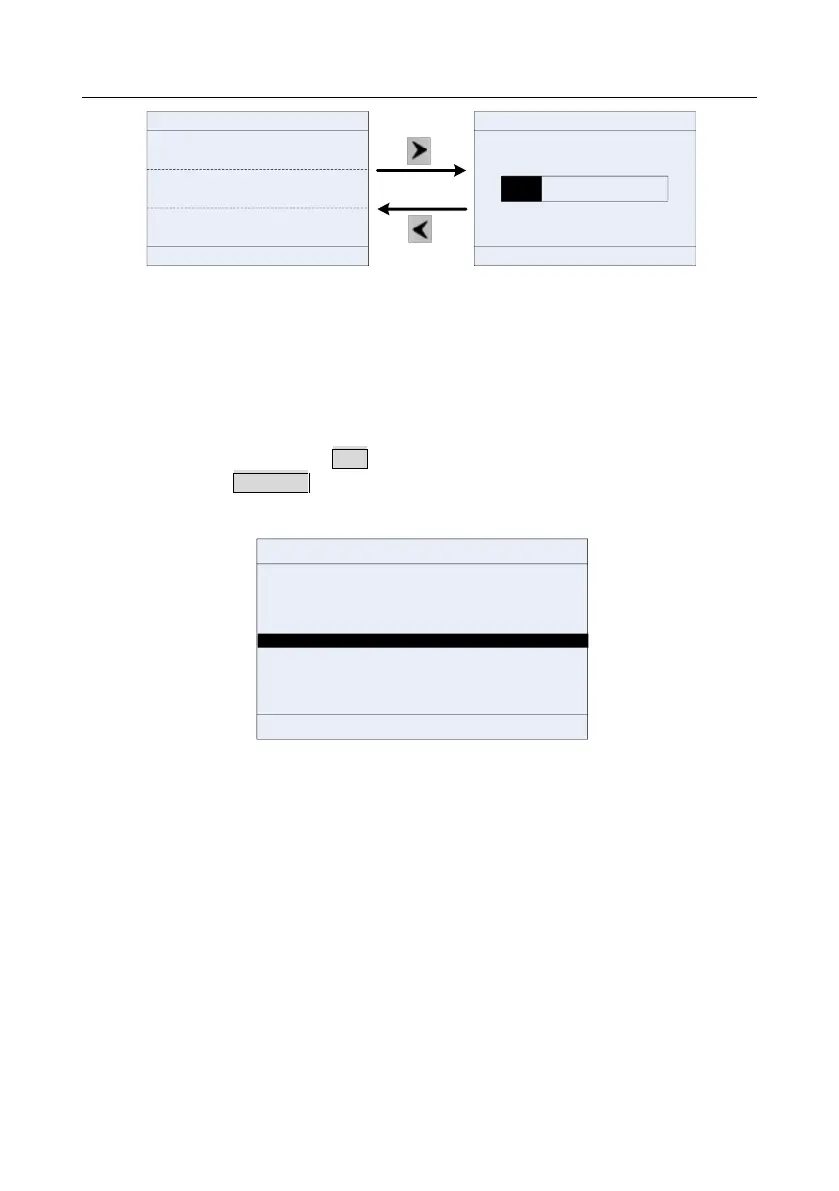
Figure 5-10 Running parameter display state
In running state, multiple kinds of state parameters can be displayed. The running display parameter
list is user defined, and each state variable function code can be added to the running display
parameter list as needed. A function code which has been added to the running display parameter list
can also be deleted or shifted.
5.3.3 Displaying fault information
The inverter enters fault alarm display state once fault signal is detected, and the keypad displays
fault code and fault information with TRIP indicator on the keypad turning on. Fault reset operation
can be carried out via STOP/RST key, control terminal or communication command.
The fault code will be kept displaying until fault is removed.
HD2
16:02:35
Fwd
Local
Fault
Home
OK
Fault code:
19:Current detection fault (ItE)
Present fault type:
19
Figure 5-11 Fault alarm display state
5.4 Operating the inverter through the keypad
Various operations can be performed on the inverter, including entering/exiting menu, parameter
selection, list modification and parameter addition.
5.4.1 Enter/exit menu
The keypad displays three main menus at the home interface by default: Parameter, About, and
Menu.
The following figure shows how to enter the Parameter main menu and how to operate under this
main menu.