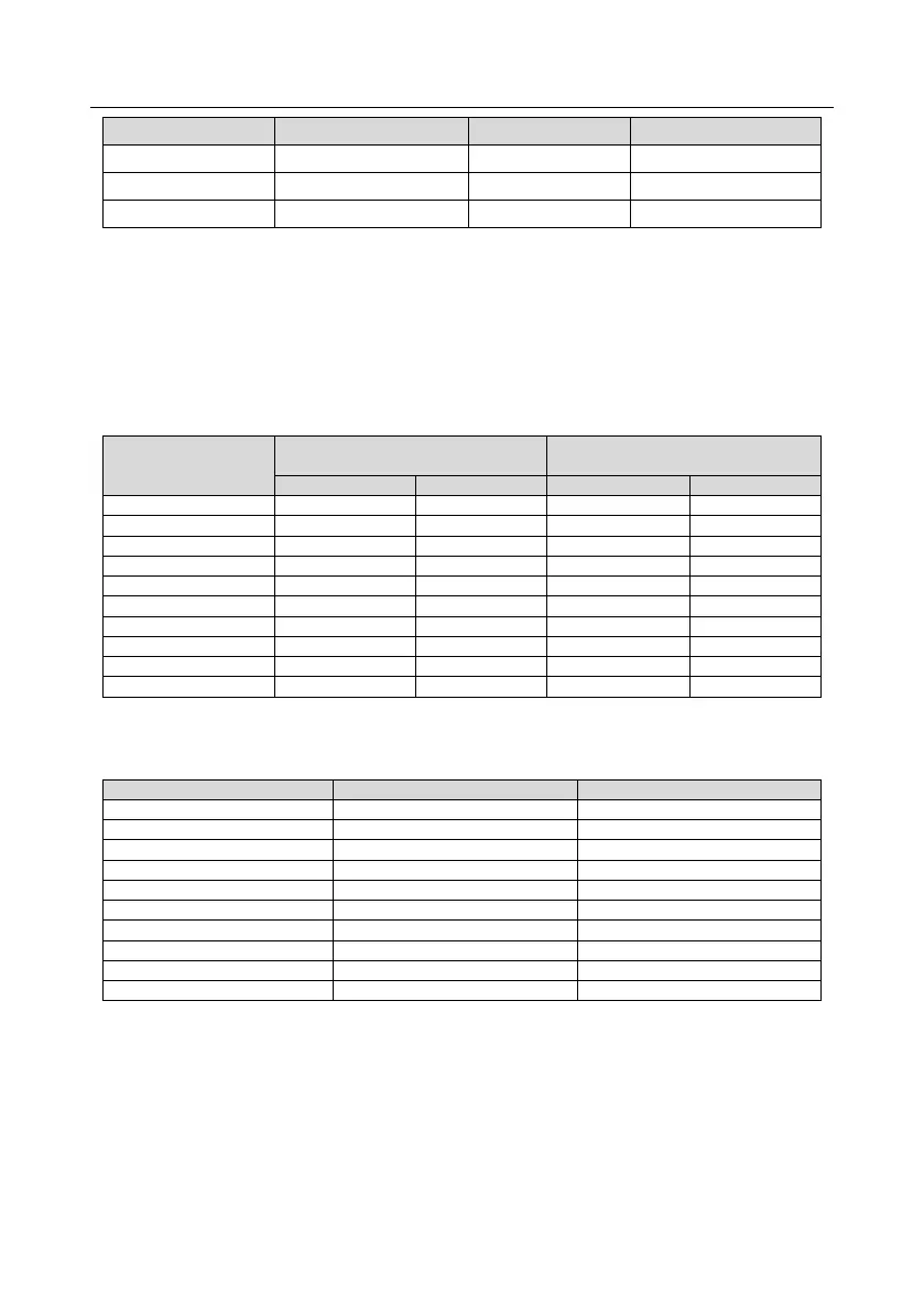
EasyManua.ls Logo

IMO HD2-3.7A-43 - 4.3.2 Wiring diagram of main circuit for parallel inverters; 4.3.3 Main circuit terminal diagram

IMO HD2-3.7A-43
408 pages
Print Icon
To Next Page IconTo Next Page
To Previous Page IconTo Previous Page
Loading...
HD2 Series Inverter Product Overview
-13-
Product model
Output power (kW)
Input current (A)
Output current (A)
HD2-150A-43
75
139
150
HD2-180A-43
90
168
180
HD2-215A-43
110
201
215
Note:
The input current of the 1.5–500kW inverter models is measured in cases where the input
voltage is 380V without additional reactors.
The rated output current is the output current when the output voltage is 380V.
Within allowable input voltage range, the output current/power cannot exceed the rated output
current/power.
3.7 Parallel inverter models
Power (kW)
380V parallel inverter
requirement
660V parallel inverter
requirement
Power (kW)
Quantity
Power (kW)
Quantity
560
280
2
-
-
630
315
2
-
-
710
350
2
350
2
800
400
2
400
2
1000
500
2
500
2
1200
400
3
630
2
1500
500
3
500
3
2000
500
4
500
4
2500
500
5
630
4
3000
500
6
630
5
3.8 Ratings of parallel products
Table 3–2 AC 3PH 380V (-15%)–440V (+10%)
Rated output power (kW)
Rated input current (A)
Rated output current (A)
560
1090
1060
630
1220
1200
710
1250
1300
800
1430
1440
1000
1780
1720
1200
2145
2160
1500
2670
2580
2000
3560
3440
2500
4450
4300
3000
5340
5160
3.9 Structure diagram
The inverter structure is shown in the following figure (taking the 380V 30kW inverter model as an
example).

Table of Contents

Related product manuals