HD2 Series Inverter Product Overview
-14-
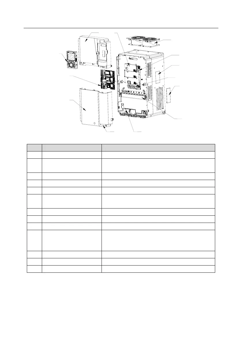
Figure 3-6 Structure diagram
Protects internal components and parts.
For details, see section 5.4 Operating the inverter through
the keypad.
Protects internal components and parts.
Optional. For details, see Appendix A Expansion Cards.
Protects the control board and install expansion card.
For details, see chapter 8 Maintenance and Hardware
Fault Diagnosis.
For details, see section 3.4 Product nameplate.
For details, see chapter 4 Installation Guidelines.
Cover plate of heat emission
hole
Optional. Cover plate can upgrade protection level,
however, as it will also increase internal temperature,
derated use is required.
For details, see chapter 4 Installation Guidelines.
For details, see section 3.5 Type designation key.