+
-
Reference-
feedback<P09.08?
P09.10
(lower limit value of PID
output)
P09.09
(upper limit value of PID
output)
0
1
P09.03
(PID output characteristics)
PID output
P17.00
P17.23
P09.08 (Limit of PID control
deviation)
P09.02
(PID feedback source)
P09.00
(PID reference source)
P17.24
PID feedback
value
PID reference
value
Set frequency
0
1
2
3
4
5
6
7
8
9
Keypad
AI1
PROFIBUS\CANopen
MODBUS
Multi-step
speed
HDIA
AI3
AI2
Ethernet
HDIB
0
1
2
3
4
5
6
7
AI1
PROFIBUS\CANopen
MODBUS
HDIA
AI3
AI2
Ethernet
Y
N
PID stops
adjustment
Pre-set PID reference of
keypad
Keep current frequency
Terminal function 25
PID control pause
Valid
Invalid
Kp P09.04 (proportional gain)
Ti P09.05 (integral time)
Td P09.06 (differential time)
P09.01
EtherCat/Profinet
PLC card
10
11
HDIB
EtherCat/Profinet
PLC card
8
9
10
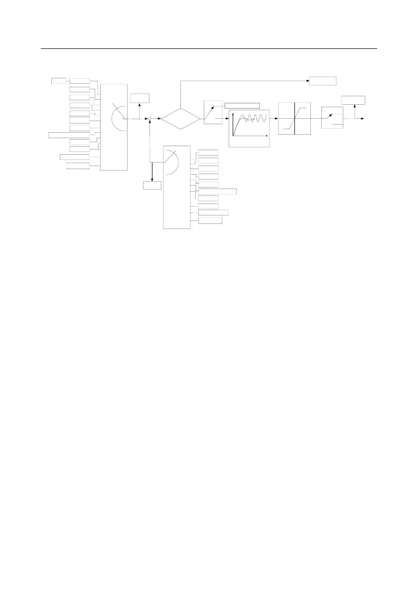
Introduction to the working principles and control methods for PID control
Proportional control (Kp): When the feedback is different from the reference, the output will be
proportional to the difference. If such a difference is constant, the regulating variable will also be
constant. Proportional control can respond to feedback changes rapidly, however, it cannot eliminate
the difference by itself. A larger proportional gain indicates a faster regulating speed, but a too large
gain will result in oscillation. To solve this problem, set the integral time to a large value and the
differential time to 0, run the system only with proportional control, and then change the reference to
observe the difference (that is, static difference) between the feedback signal and reference. If the
static difference occurs in the direction of reference change (such as reference increase, where the
feedback is always less than the reference after system stabilizes), continue increasing the
proportional gain; otherwise, decrease the proportional gain. Repeat this process until the static
difference becomes small.
Integral time (Ti): When feedback deviates from reference, the output regulating variable accumulates
continuously, if the deviation persists, the regulating variable will increase continuously until deviation
disappears. Integral regulator can be used to eliminate static difference; however, too large regulation
may lead to repetitive overshoot, which will cause system instability and oscillation. The feature of
oscillation caused by strong integral effect is that the feedback signal fluctuates up and down based
on the reference variable, and fluctuation range increases gradually until oscillation occurred. Integral
time parameter is generally regulated gradually from large to small until the stabilized system speed
fulfills the requirement.
Derivative time (Td): When the deviation between feedback and reference changes, output the
regulating variable which is proportional to the deviation variation rate, and this regulating variable is
only related to the direction and magnitude of the deviation variation rather than the direction and
magnitude of the deviation itself. Differential control is used to control the feedback signal variation