HD2 Series Inverter Basic Operation Guidelines
-121-
In position control mode, you can check the high bit and low bit of position reference and feedback,
P18.02 (count value of Z pulse), P18.00 (actual frequency of encoder), P18.17 (pulse command
frequency), and P18.19 (position regulator output), through which you can figure out the relation
between P18.08 (position of position reference point) and P18.02 (count value of Z pulse), and
between P18.17 (pulse command frequency), P18.18 (pulse command feedforward) and P18.19
(position regulator output).
Step 6: The position regulator has two gains, namely P21.02 and P21.03, and they can be switched
by speed command, torque command and terminals.
Step 7: When P21.08 (output limit of position controller) is set to 0, the position control will be invalid,
and at this point, the pulse string acts as frequency source, P21.13 (position feedforward gain) should
be set to 100%, and the speed acceleration/deceleration time is determined by the acceleration
/deceleration time of pulse string, the pulse string acceleration/deceleration time of the system can be
adjusted. If the pulse string acts as the frequency source in speed control, you can also set P21.00 to
0000, and set the frequency source reference P00.06 or P00.07 to 12 (set by pulse string AB), at this
point, the acceleration/deceleration time is determined by the acceleration/deceleration time of the
inverter, meanwhile, the parameters of pulse string AB is still set by P21 group. In speed mode, the
filter time of pulse string AB is determined by P21.29.
Step 8: The input frequency of pulse string is the same with the feedback frequency of encoder pulse,
the relation between them can be changed by altering P21.11 (numerator of position command ratio)
and P21.12 (denominator of position command ratio)
Step 9: When running command or servo enabling is valid (by setting P21.00 or terminal function 63),
it will enter pulse string servo running mode.
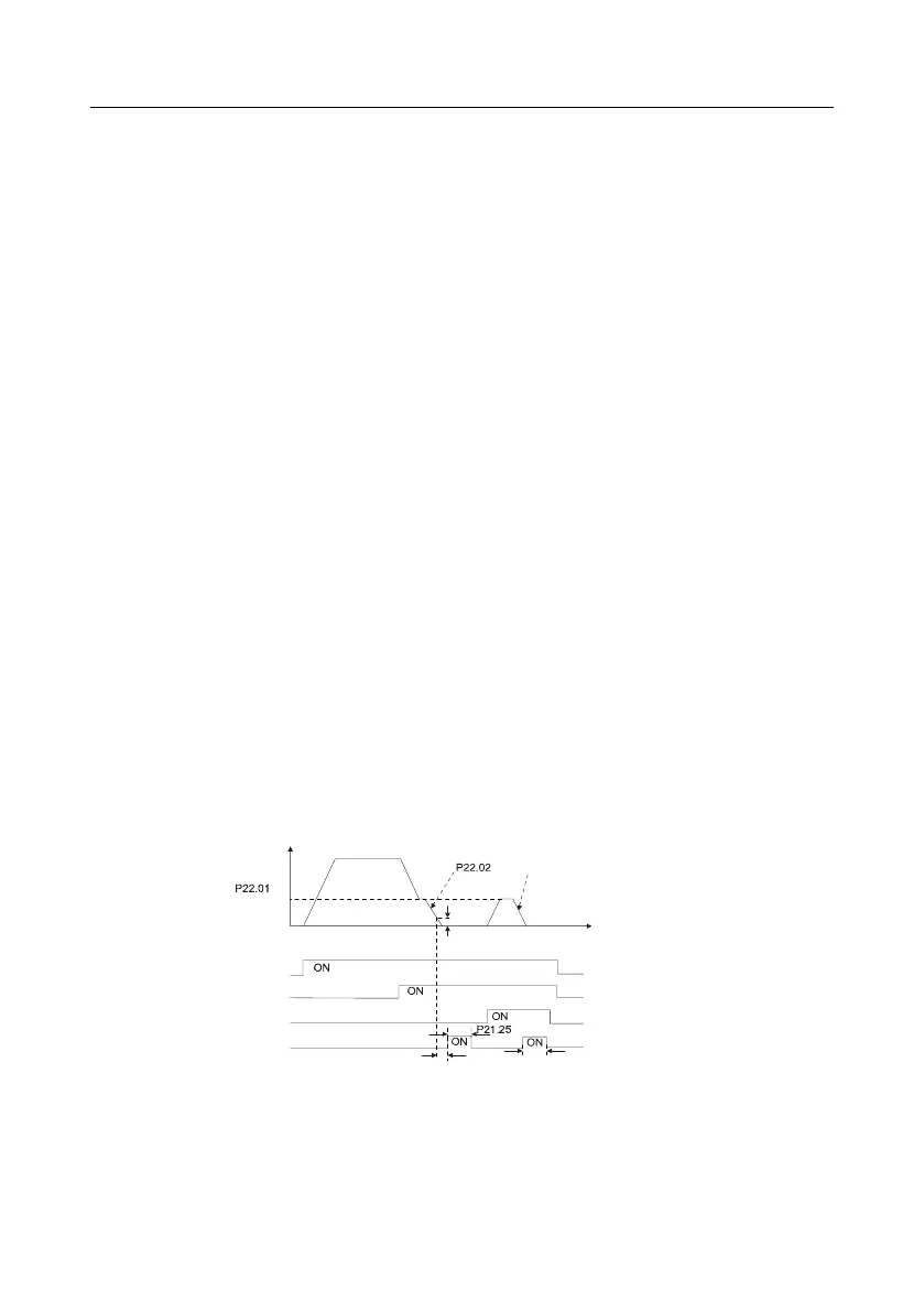
4. Commissioning procedure for spindle positioning
Spindle orientation is to realize orientation functions like zeroing and division based on closed-loop
vector control
Frequency
Deceleration time of spindle orientation
Speed of
accurate-stop
of spindle
Time
P21.09 Completion
range of positioning
Running command
Zeroing command
Zeroing selection terminal 1
Positioning completion signal
Hold time of positioning completion signal
P21.10 Detection time
for positioning completion
P21.25 Hold time of positioning completion signal
Step 1–4: These four steps are the same with the first four steps of the commissioning procedures for
closed-loop vector control, which aim to fulfill the control requirements of closed-loop vector control,
thus realizing spindle positioning function in either position control or speed control mode.