HD2 Series Inverter Basic Operation Guidelines
-123-
a) the encoder is installed on the motor shaft; the motor shaft and spindle are 1:1 rigid
connection.
b) the encoder is installed on the motor shaft; the motor shaft and spindle are 1:1 belt connection.
At this point, the belt may slip during high-speed running and cause inaccurate positioning, it is
recommended to install proximity switch on the spindle.
c) The encoder is installed on the spindle, and the motor shaft is connected to the spindle with
belt, the drive ratio is not necessarily 1:1.
At this point, set P20.06 (speed ratio of the mounting shaft between motor and encoder), and set
P22.14 (spindle drive ratio) to 1. As the encoder is not installed on the motor, the control performance
of closed-loop vector will be affected.
Proximity switch positioning supports the following spindle positioning modes:
a) The encoder is installed on the motor shaft, the drive ratio between motor shaft and spindle is
not necessarily 1:1.
At this point, it is required to set P22.14 (spindle drive ratio).
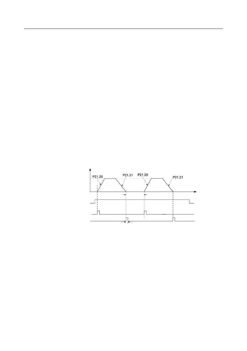
5. Commissioning procedure for digital positioning
The diagram for digital positioning is shown below.
Step 1–4: These four steps are the same with the first four steps of the commissioning procedures for
closed-loop vector control, which aim to fulfill the control requirements of closed-loop vector control.
Step 5: Set P21.00=0011 to enable digital positioning. Set P21.17, P21.11 and P21.12 (set
positioning displacement) according to actual needs; set P21.18 and P21.19 (set positioning speed);
set P21.20 and P21.21 (set acceleration/deceleration time of positioning).
Step 6: Single positioning operation
Set P21.16. bit1=0, and the motor will carry out single positioning action and stay in the positioning
position according to the setup in step 5.
Step 7: Cyclic positioning operation
Set P21.16. bit1=1 to enable cyclic positioning. The cyclic positioning is divided into continuous mode
and repetitive mode; you can also carry out cyclic positioning through terminal function (no. 55,