HD2 Series Inverter Communication
-323-
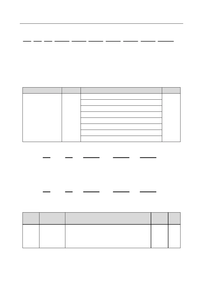
Assume that the following response is returned:
VFD
address
Read
command
Number of
bytes
Last fault
type
Most recent
fault type
2nd-last fault
type
CRC
3rd-last fault
type
4th-last fault
type
5th-last fault
type
03 03 0C 00 23 00 23 00 23 00 23 00 2300 23 5F D2
From the returned data, we can see that all the fault types are 0023H, that is, 35 in the decimal form,
which means the maladjustment fault (STo).
9.4.8.2 Write command 06H examples
Example 1: Set the inverter whose address is 03H to be forward running. Refer to the table of other
function parameters, the address of "Communication-based control command" is 2000H, and 0001H
indicates forward running, as shown in the following table.
Communication-based
control command
The command transmitted by the master is as follows:
Parameter
address
CRC
VFD
address
Write
command
Forward
running
03 06 20 00 00 01 42 28
If the operation is successful, the following response is returned (same as the command transmitted
by the master):
Parameter
address
CRC
VFD
address
Write
command
Forward
running
03 06 20 00 00 01 42 28
Example 2: Set the "Max. output frequency" of the inverter whose address is 03H to 100 Hz.
Used to set the maximum output frequency of the
inverter. It is the basis of frequency setup and the
acceleration/deceleration.
Setting range: Max (P00.04, 10.00) –630.00Hz
From the number of decimals, we can see that the fieldbus scale of the "Max. output frequency"
(P00.03) is 100. Multiply 100 Hz by 100. The value 10000 is obtained, and it is 2710H in the
hexadecimal form.