HD2 Series Inverter Expansion Cards
-336-
On: The expansion card is establishing a
connection with the control board.
Blinking periodically: The expansion card is
properly connected to the control board (the
period is 1s, on for 0.5s, and off for the other
0.5s).
Off: The expansion card is disconnected
from the control board.
On: The control board feeds power to the
expansion card.
The HD2-E-IO expansion card can be used in scenarios where the I/O interfaces of a HD2-UL
inverter cannot meet the application requirements. It can provide 4 digital inputs, 1 digital output, 1
analog input, 1 analog output, and two relay outputs. It is user-friendly, providing relay outputs
through European-type screw terminals and other inputs and outputs through spring terminals.
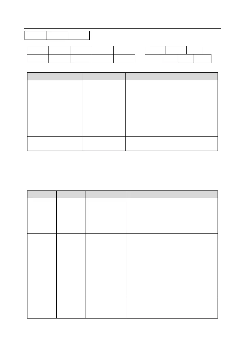
HD2-E-IO terminal function description
The working power of digital input is
provided by an external power supply.
Voltage range: 12–30 V
The terminals PW and +24V are shorted
before delivery.
1. Input range: 0–10 V, 0–20 mA
2. Input impedance: 20 kΩ for voltage input;
250 Ω for current input
3. Set it to be voltage or current input
through the corresponding function code.
4. Resolution: When 10 V corresponds to
50 Hz, the minimum resolution is 5 mV.
5. Deviation: ±0.5%; input of 5 V or 10 mA
or higher at the temperature of 25°C
1. Output range: 0–10 V, 0–20 mA
2. Whether it is voltage or current output is
determined by J5.