HD2 Series Inverter Expansion Cards
-340-
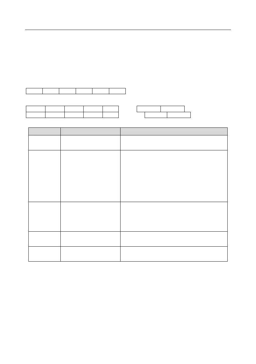
SW1 is the start/stop switch of the programmable expansion card. CN1 contains terminals PE, 485-,
485+, GND, AI1, and AO1, and a selection jumper resides on the next. "AI" and "AV" are the current
type input selection and voltage type input selection of AI1, and they can be selected through J2.
"AIO" and "AVO" are the current type output selection and voltage type output selection of AO1, and
they can be selected through J5. "120" indicates 120Ω terminal resistor, and it can connect to J1. By
default, J1 connects to NC, J2 to AV, and J5 to AVO.
The terminals are arranged as follows.
PWR power indicator
(green)
The indicator is on when the expansion card is
powered on.
COMM communication
indicator (green)
This indicator is on when the expansion card is
establishing a connection with the control board.
it blinks periodically after the expansion card is
properly connected to the control board (the period
is 1s, on for 0.5s, and off for the other 0.5s);
and it is off when the expansion card is
disconnected from the control board.
ERR fault indicator (red)
Blinks: an error occurs (the period is 1s, on for 0.5s,
and off for the other 0.5s), and the error type can be
queries through the upper computer Auto Station;
Off: no fault.
PWR power indicator
(green)
The indicator is on when the expansion card is
powered on.
RUN status indicator (green)
On: PLC program is running
Off: PLC program stops
The HD2-E-PLC programmable expansion card can replace some micro-PLC applications. It adopts
the global mainstream development environment PLC, supporting the instruction language (IL),
ladder diagram (LD), and sequential function chart (SFC). It provides a user program storage space
of 16K steps and data storage space of 8K words and supports saving data of 1K words at power
failure, which facilitate customers' secondary development and meets the customization
requirements.
The HD2-E-PLC programmable expansion card provides 6 digital inputs, 2 relay outputs, 1 analog
input, 1 analog output, 1 RS485 communication channel (supports master/slave switchover). It is
user-friendly, providing relay outputs through European-type screw terminals and other inputs and