HD2 Series Inverter Expansion Cards
-349-
(Maintenance state
indicator)
the characteristics of the device
LED6/7
(Network port state
indicator)
PROFINET communication card and
PC/PLC have been connected through
a network cable.
PROFINET communication card and
PC/PLC have not been connected.
LED8/9
(Network port
communication
indicator)
PROFINET communication card and
PC/PLC are communicating.
PROFINET communication card and
PC/PLC are not communicating.
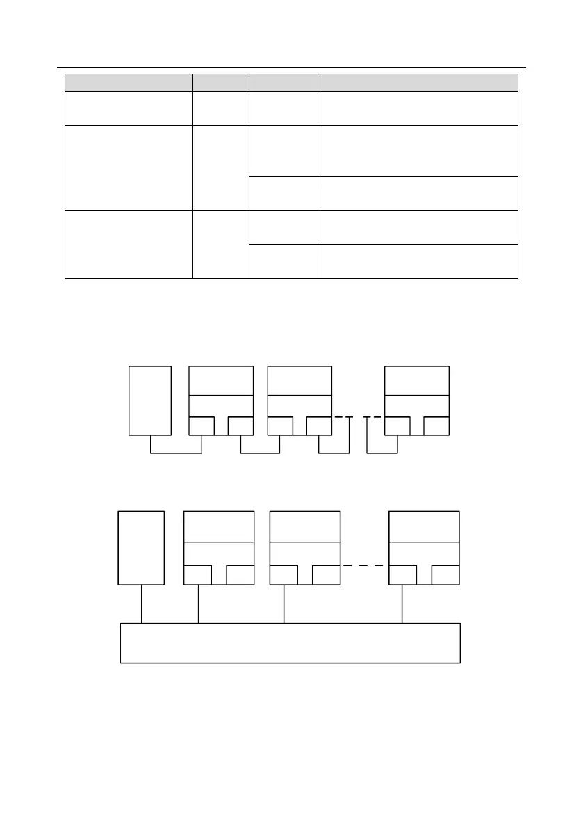
Electrical connection
The PROFINET communication card adopts a standard RJ45 interface and can adopt the linear
network topology or star network topology. The electrical connection in linear network topology mode
is shown in the following.
Master
device
Slave device 2
RJ45
RJ45
Slave device 1
RJ45
RJ45
Slave device n
RJ45
RJ45
Note: For the star network topology, you need to prepare PROFINET switches.
The electrical connection in start network topology mode is shown in the following.
Master
device
Slave device 2
RJ45
RJ45
Slave device 1
RJ45
RJ45
Slave device n
RJ45
RJ45
Switch