HD2 Series Inverter Expansion Cards
-364-
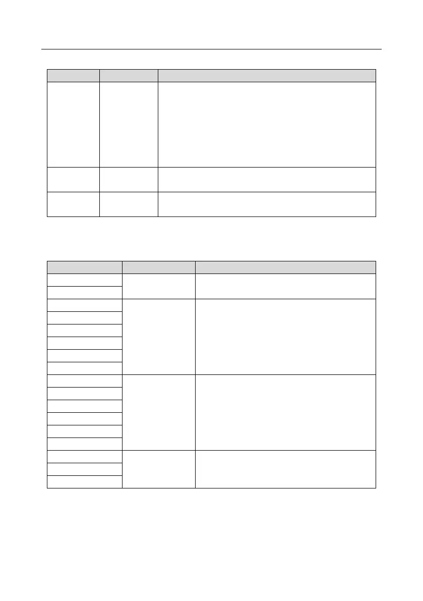
Indicator definition
On: The expansion card is establishing a connection with the
control board.
Blinking periodically: The expansion card is properly
connected to the control board (the period is 1s, on for 0.5s,
and off for the other 0.5s).
Off: The expansion card is disconnected from the control
board.
This indicator blinks only if A1 or B1 signal is disconnected
during encoder rotating; and it is on in other cases.
On: The control board feeds power to the PG card.
HD2-E-PGIM24 can work in combination with multiple types of incremental encoders through various
external wiring modes. It is user-friendly, adopting spring terminals.
HD2-E-PGIM24 terminal function description
Voltage: 24 V ± 5%
Max. output current: 150 mA
1. Supporting 24 V push-pull interfaces
2. Supporting 24 V open collector interfaces
3. Frequency response: 200 kHz
1. Supporting interfaces whose signal type is the
same as the encoder
2. Frequency response: 200 kHz
1. Open collector output
2. Supporting frequency division of 1–255, which
can be set through P20.16 or P24.16