HD2 Series Inverter Basic Operation Guidelines
-58-
curve corresponds to power 1.3, 1.7 or 2.0.
Output voltage
Output frequency
Straight-type
Torque -down V/F curve (power of 1.3)
Square-type
Torque -down V/F curve (power of 1.7)
Torque -down V/F curve (power of 2.0)
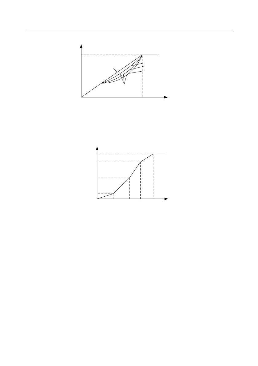
The inverter also provides multi-point V/F curve. You can alter the V/F curve outputted by inverter
through setting the voltage and frequency of the three points in the middle. The whole curve consists
of five points starting from (0Hz, 0V) and ending in (fundamental motor frequency, rated motor
voltage). During setting, follow the rule: 0 ≤ f1 ≤ f2 ≤ f3 ≤ Motor fundamental frequency, and 0 ≤ V1 ≤
V2 ≤ V3 ≤ Motor rated voltage
Output voltage
f1
f2
f3
V1
V2
V3
The inverter provides dedicated function codes for SVPWM control mode. You can improve the
performance of SVPWM through settings.
1. Torque boost
Torque boost function can effectively compensate for the low-speed torque performance during
SVPWM control. Automatic torque boost has been set by default to enable the inverter to adjust the
torque boost value based on actual load conditions.
Note:
(1) Torque boost is effective only under torque boost cut-off frequency.
(2) If the torque boost is too large, low-frequency vibration or overcurrent may occur to the motor, if
such situation occurs, lower the torque boost value.