HD2 Series Inverter Basic Operation Guidelines
-61-
acceleration/deceleration time of voltage and frequency respectively, which will form a real-time V/F
curve through combination.
Note: This kind of V/F curve separation can be applied in various frequency-conversion power
sources, however, you should be cautious of parameter setup as improper setup may damage the
machine.
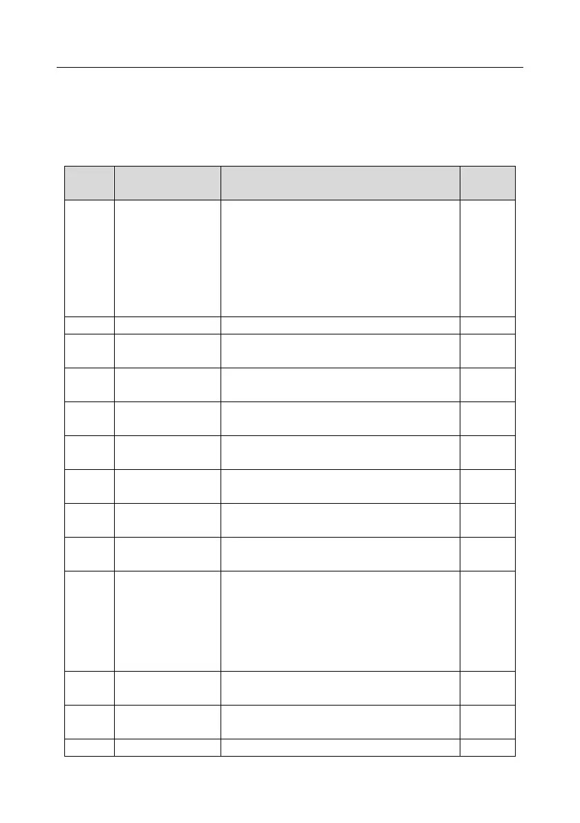
0: Sensorless vector control (SVC) mode 0
1: SVC 1
2: Space voltage vector control mode
3: FVC
Note: To select 0, 1, or 3 as the control mode,
enable the inverter to perform motor parameter
autotuning first
Upper limit of running
frequency
Lower limit of running
frequency
0: Asynchronous motor
1: Synchronous motor
Rated power of
asynchronous motor 1
0.01Hz–P00.03 (Max. output frequency)
Rated voltage of
asynchronous motor 1
V/F curve setting of
motor 1
0: Straight-type V/F curve
1: Multi-point V/F curve
2: Torque-down V/F curve (power of 1.3)
3: Torque-down V/F curve (power of 1.7)
4: Torque-down V/F curve (power of 2.0)
5: Customized V/F (V/F separation)
0.0%: (automatic) 0.1%–10.0%
Motor 1 torque boost
cut-off
0.0%–50.0% (rated frequency of motor 1)