Chapter 5 Relay Ladder Logic Programming 112
-
The state of M01, M02 and M03 decide the duty cycle and frequency of PWM output. PWM stages can be
changed by the status of M01, M02 and M03 when P01 is running. ⑥ displays the number of pulse when P01 is
running, but ⑥ equals 0 when P01 is disabled.
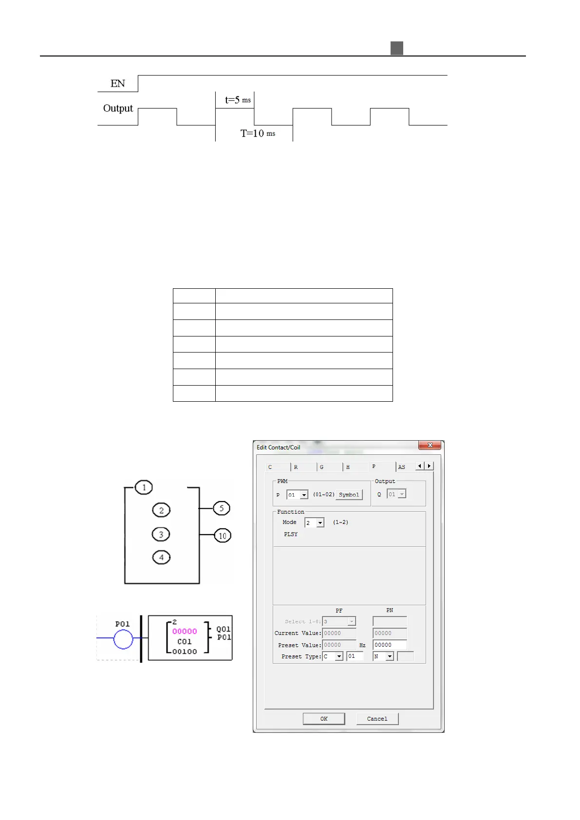
Mode2 PLSY
Only P01 can work under this mode, and the output is Q01. PLSY has 6 parameters for proper
configuration. The table below describes the information of PLSY parameters.
①
②
Total number of pulse (storing in DRC9)
③
Preset frequency of PLSY (1~1000Hz)
④
Preset pulse number of PLSY(0~32767)
⑤
⑥
Example:
 Loading...