Chapter 5 Relay Ladder Logic Programming 72
-
5BTimer Instruction
The iSmart includes 31 Timer coils that can be used throughout a program. T0E
and T0F keep their current value after power lost if “M Keep” is active, but the other
Timers’ current value is non-retentive. Each Timer has a choice of 8 operation modes,
1 for a pulse Timer and 7 for general purpose Timer. Additionally, each Timer has 6
parameters for proper configuration. The table below describes each configuration
parameter and lists each compatible element for configuring Timers.
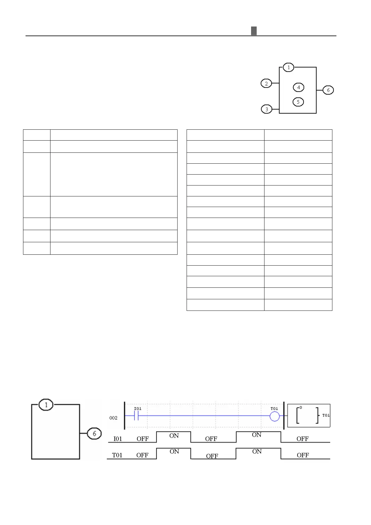
①
②
Timer Unit 1: 0.01s, range: 0.00 - 99.99 sec
2: 0.1s, range: 0.0 - 999.9 sec
3: 1s, range: 0 - 9999 sec
4: 1min, range: 0 - 9999 min
③
OFF: the Timer continues timing
④
⑤
⑥
Timer code(T01~T1F total: 31 Timers)
※ The preset value of Timer could be a constant or other function current value.
※ The current value of T0E and T0F will be kept when iSmart on a loss of power if the “M-Keep” is active.
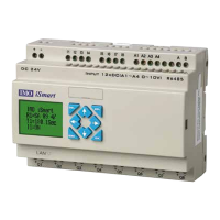
Timer Mode 0 (Internal Coil)
Mo
de 0 Timer (Internal Coil) used as internal auxiliary coils. No timer preset value. The status of T coil becomes
with enable coil as shown below.
※
I01 is enable coil.