Chapter 5 Relay Ladder Logic Programming 71
-
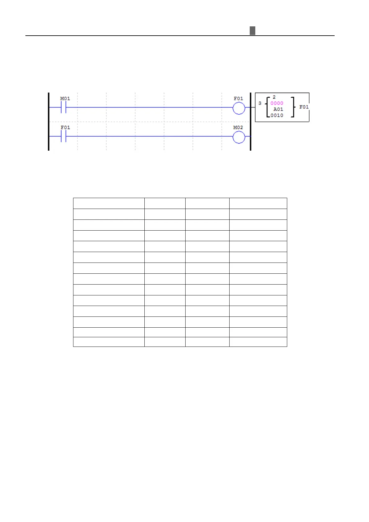
Filter coil (F)
The status of filter decided by the setting of Filter conditions;
If the filter reaches filter conditions, function block current will be updated, filter current value will display
filter result, filter coil will be ON.
According to the photo below, coil (F01) will be output when enabled coil (M01) 10 seconds, current value will
be updated.
Analog Elements
Ana
log value (A01~A08, V01~V08, AT01~AT04, AQ01~AQ04, (NI01~NI1F, NQ01~NQ0F)) and current value
of functions (T01~T1F, C01~C1F, AS01~AS1F, MD01~MD1F, PI01~PI0F, MX01~MX0F, AR01~AR0F, and
DR01~DRF0) can be used as other function’s preset value. And the parameter preset value is its limit value when the
current value of those functions is bigger or less than parameter’s limit value.