Chapter 5 Relay Ladder Logic Programming 69
-
2BSpecialty Elements
output
output
output
output
contact
contact
Number
pulse output)
D d
Po
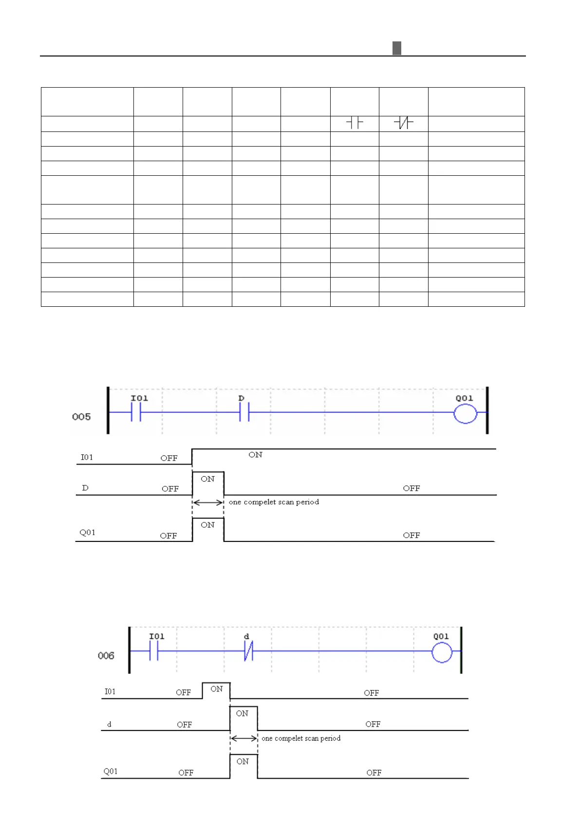
sitive Edge Trigger - Pulse Output ( D )
A positive edge trigger (D) holds its status ON for one CPU scan time when the preceding series contact changes
its state from OFF to ON. The transition from OFF to ON is called the “Positive Edge Trigger”.
Ne
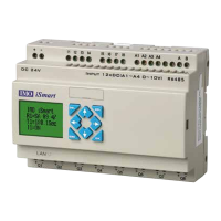
gative Edge Trigger - Pulse Output ( d )
A negative edge trigger (d) holds its status ON for one CPU scan time when the preceding series contact changes
its state from ON to OFF. The transition from ON to OFF is called the “Negative Edge Trigger”.