Chapter 5 Relay Ladder Logic Programming 129
-
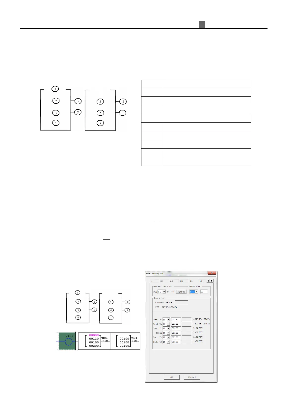
17BPID (Proportion- Integral- Differential)
The iSmart smart relay includes 15 PID coils that can be used throughout a program. The PID function performs a
simple integral-math-calculation which is according to the equation as shown in below. There are 9 parameters for
proper configuration. The table below describes each configuration parameter and lists each compatible element for
configuring PID.
Th
e parameters from ① to ⑦ can be a constant or refer to the current value of other function The error coil
will turn ON when either T
S
or K
P
equal to 0. But it will do nothing if the output coil is N O P. The output coil will turn
OFF when the result is in the range, or the function is disabled.
PID computes formula:
( )
( )
∑
∆=
−−=
++−=∆
−=
−−
−
PIPI
PVPVPV
T
T
D
DEV
T
T
EVEVKPI
PVSVEV
nnn
S
D
n
nn
I
s
nnP
nn
21
1
2
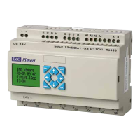
The example below shows how to configure PID function.
①
PI: PID current value (-32768~32767)
②
SV: Set value (-32768~32767)
③
PV: Feedback value (-32768~32767)
④
S
: Sampling time (1~32767 * 0.01s)
⑤
P
: Proportional gain (1~32767 %)
⑥
I
: Integration time (1~32767 * 0.1s)
⑦
D
: Differential time (1~32767 * 0.01s)
⑧
Error output coil (M, N, NOP)
⑨