Chapter 8 20 Points RS485 type Models Instruction 206
Detail instruction
Remote IO function
Function Description:
Remote IO function can make one iSmart as master link to another iSmart as slave; the master can perform its
program, but the slave cannot. The ON/OFF state of the output coil Q in slave will affect the ON/OFF state of the
expansion output coil Y in master. In addition, the ON/OFF state of input coil X in master depends on the state of the
input coil I in slave.
I/O Address Master Slave
Input Coils I01~I0C
Output Coils Q01~Q08
Expansion Input Coils X01~X0C I01~I0C
Expansion Output Coils Y01~Y08 Q01~Q08
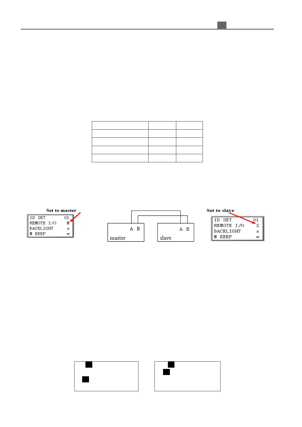
Hardware Configuration:
1. Link two “CD” type iSmart as illustration show below.
2. Assign left iSmart in the illustration as master.
3. Set another iSmart to Slave.
The program in master is valid, but the one in slave is not.
Do not use expansion DI/DO modules, when remote I/O function is enabled.
Example:
Create a Ladder program as show below is written in master.
X02――――――― Y01
X03――――――― Y02
If input coils I02 and I03 in the Slave turn ON. X02 and X03 in master will also turn ON due to the influence of
I02 and I03 in the Slave. Obviously, Y01 and Y02 in the master will turn ON, and then it causes Q1 and Q2 switching
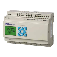
ON. See the consequence on the IO interface as shown in below.
I/O State on Slave Run mode I/O State on Master Run mode
I .1 2 3 4 5 6 7 8 9 0 A B C
Z.1 2 3 4
Q.1 2 3 4 5 6 7 8 9 0 A B C
MO 14 : 42
X. 1 2 3 4 5 6 7 8 9 0 A B C
Y. 1 2 3 4 5 6 7 8 9 0 A B C
EXE
2010.05.09