Chapter 6 FBD Block Diagram Programming 195
DR (Data-Register) function block
There is a maximum of 240 DR (data register) function blocks under FBD mode, and the function is same as Ladder
mode.
The DR function is transferring data. DR sends data from prevention registers to current register and output coil Bxxx
ON when it is enabled. DR holding the out value and output coil Bxxx OFF when it is disabled.
The data can be signed or unsigned by Operation>>module system set…menu selection from the SMT Client
software or keypad set.
The data registers from DR65 to DRF0 will be kept when the smart stop or powers down.
The last 40 DR that from DRC9 to DRF0 are special data register, more information to see Chapter 3 Program
Tools—Data Register Set.
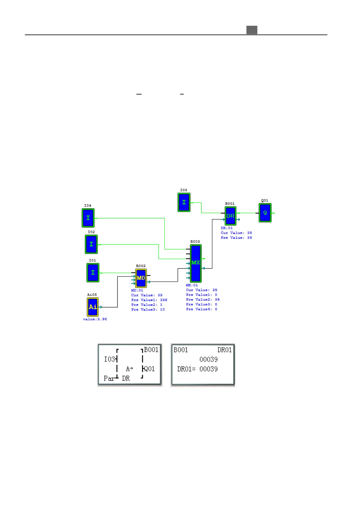
Example:
Setting I02 ON, B001 (DR01) output (A05*1/10) count value;
Setting I02 OFF, B001 (DR01) output 0;
Current value
(run mode)
(DR01=B003
stop mode)