Chapter 5 Relay Ladder Logic Programming 66
-
1BBasic Elements
output
output
output
output
contact
contact
Number
Input
Z z 4(Z01-Z04/z01-z04)
Output
Q Q Q Q Q q 8(Q01-Q08/q01-q08)
Coil
M M M M M m 127(M01-M7F/m01-m7F)
Coil
N N N N N n 127 (N01-N7F/n01-n7F)
Input
J j 6
3(J01-J3F/j01-j3F)
Output
K K K K K k 63(K01-K3F/k01-k3F)
Digital Inputs ( I )
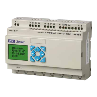
The iSmart digital input points are designated as I contacts. The number of digital input points is 6, 8 or 12
depending on each iSmart model.
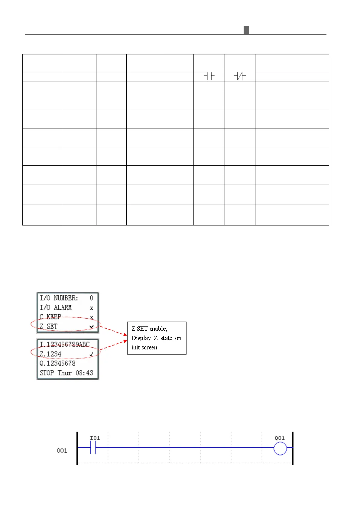
Keypad Inputs ( Z )
The iSmart keypad input points are designated as Z contacts. The number of keypad input points is 4 which only
exist on SMT CD type model and ED type model.
D
igital Outputs ( Q )
The iSmart digital output points are designated as Q coils/contacts. The number of digital output points is 4 or 8
depending on each iSmart model. In this example, output point Q01 will be turned on when input point I01 is
activated.