Chapter 5 Relay Ladder Logic Programming 67
-
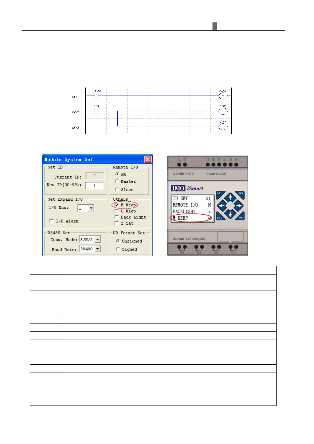
Auxiliary Coils ( M )
Auxiliary Coils are the virtual coils inside the iSmart unit; they are not the real physically inputs or outputs that
can be wired to any external devices, switches, sensors, etc. The number of Auxiliary Relays M is 127. Since
auxiliary relays are internal elements within the CPU, they can be programmed as digital inputs (contacts) or digital
outputs (coils). In the first rung of this example, auxiliary relay M01 is being used as an output coil and will energize
when input I02 turns on. In the second rung auxiliary relay M01 is being used as an input and when energized, will
turn on outputs Q02 and Q03.
※
The state of auxiliary relays “M01~M3F” will be kept when the smart powers down if “M Keep” is active. “
M
Keep” can be set by the two ways below.
Sp
ecial Auxiliary Relays: M31~M3F
User program upstart flag
Outputting ON during the first scanning period; and used as
normal auxiliary relay at other scan period.
Summertime turn ON, winter time turn OFF, used as normal
auxiliary relay.
Output ON when the first channel of SMT-4PT error is
Output ON when the second channel of SMT-4PT is error
Output ON when the third channel of SMT-4PT is error
Output ON when the fourth channel of SMT-4PT is error
Output ON when the RS485 port has received data.
Output ON when the RS232 port has received data.
Counter mode9 “high speed input counter” Counter direction
MODBUS function using
(MU instruction)