Chapter 6 FBD Block Diagram Programming 147
IO Link function block
Up to 8 additional iSmart units can be configured as independent Slave nodes, each running their own logic program
and their I/O linked to one Master smart relay. The Master iSmart smart relay’s ID must be 00, and Slave nodes’
ID should start with 01 and be continuous. If nodes’ ID is not continuous, the Master will not communicate with
those nodes which are behind the first broken. For example, the nodes’ ID is 01, 02, 04 and 05. The Master
thinks there are only two Slave nodes whose ID is 01 and 02, and communication with them.
Each controller can use 8 IO Link (L01~L08). Only one IO Link instruction can work at Mode 1(Send mode),
and the other IO Link instructions must be Mode 2 (Receive mode).
The Mode 1: Send memory range is determined by the Controller ID. The adjacent table show the memory range of
Wxx locations associated with each controller ID.
The Mode 2: read the selected Wxx status and write to the selected coil. If the select coil type is input coil I or X, coil
status cannot be changed by Wxx status.
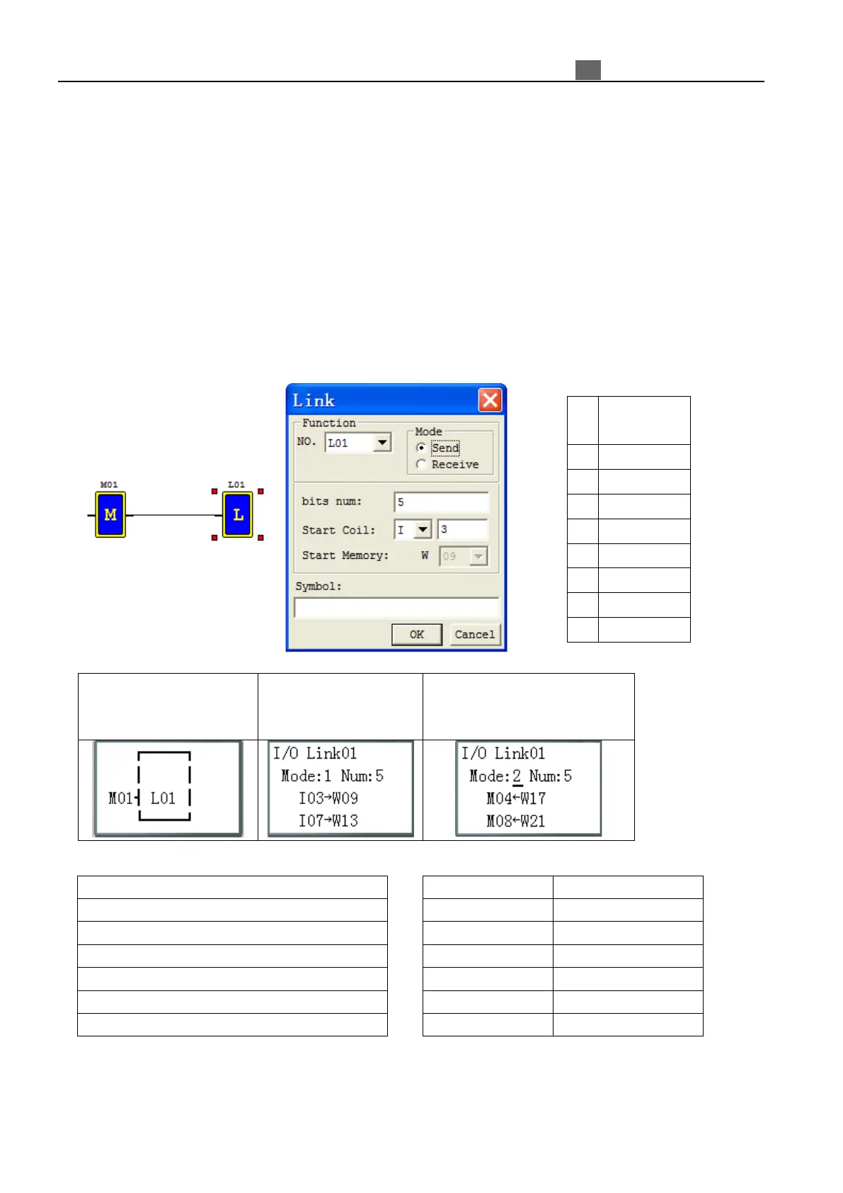
FBD output coil display
M01: enable input coil
Press “OK” button into
function display
Press “SEL” , “↑ ↓” and “OK”
to modify mode, coil number,
coil type and W address
L01: I/O link output terminal (L01~L08)
M01: Enable Input (I01~ B260)
Mode: Setting mode(1,2) 1:sending; 2:receiving
Num: Number of send/receive points (1~8)
I03…I07: Type of send/receive points
W09…W13: Send/Receive W Table list location
location