Chapter 6 FBD Block Diagram Programming 148
Example 1: IO Link Mode 1
Set mode=1, num=5, set type of points as I03, the state of actual sending terminal I03~I07 is sent to memory list; the
controller ID=1, the state of corresponding memory list position W09~W13, and relationship of sending terminal is as
below:
mode=1, num=5, type=I03~I07, ID=1 (W09~W13)
Or sending terminal
I03
I04
I05
I06
I07
0
0
0
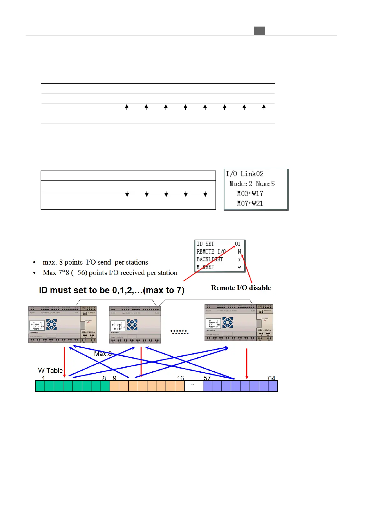
Example 2: IO Link Mode 2
Set mode=2, num=5, set type of points as start from M03, set W table as from W17, when enabling the IO Link,
the state “ON/OFF” of M03~M07 is controlled by the state of memory list position W17~W21.
Mode=1, num=5, type=M03~M07, W=W17~W21
Or sending terminal
M03
M04
M05
M06
M07
IO Link diagram as blow:
※ More information about IO Link to see “Chapter 7 20 Points RS485 type Models Instruction”.