Chapter 8 20 Points RS485 type Models Instruction 211
Modbus RTU slave function
Function Description:
iSmart unit can be controlled by the computer or other controller using the communication control. PC and other
controller can read and write IO state, preset value of the elements and the setting of the unit. It also can use to read
the current value of the element and control the Run/Stop mode of iSmart. The maximum frame length in
communication format is 128bytes.
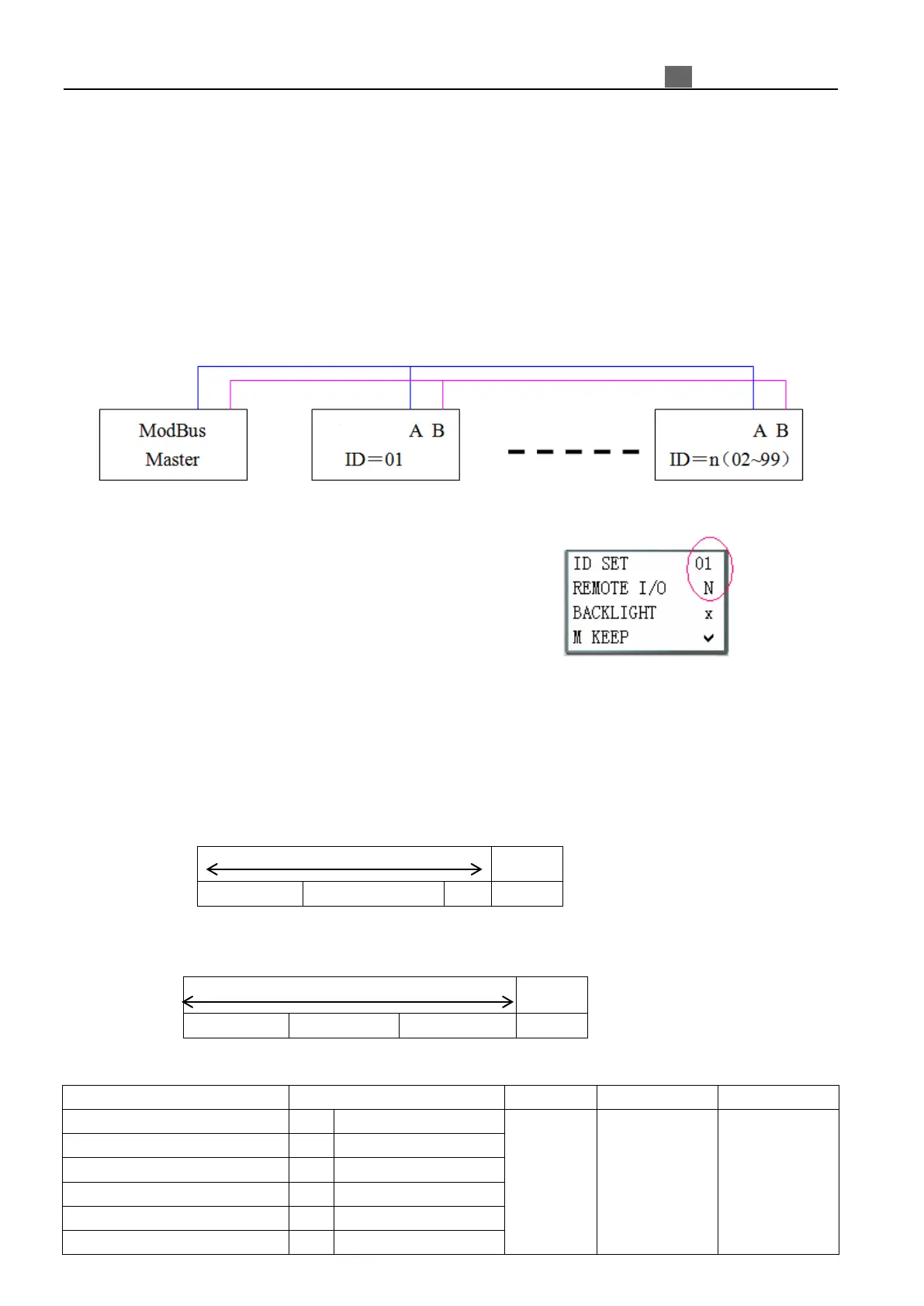
Hardware Configuration:
1. Connect the RS485 port A on each iSmart unit together, also do it to port B, as shown in below figure.
2. Set iSmart in the SET menu to No Remote IO.
3. Set iSmart ID = 01~99.
iSmart Modbus protocol
If iSmart receive a correct frame, it will carry out the command, its responses a correct frame to computer or
other controller. If the command that iSmart received is incorrect, iSmart responses Exception code to computer or
controller.
● Command format and Response format
● The Response command format, once iSmart receive an unexpected command.
Command Format:
00H: broadcast to all the drivers
For detail
please refer
register
address
CRC verifying
range contain
Slave Address
Function Code
Exception Code
For detail,
please refer
Exception Code
Instruction
 Loading...