Chapter 5 Relay Ladder Logic Programming 81
-
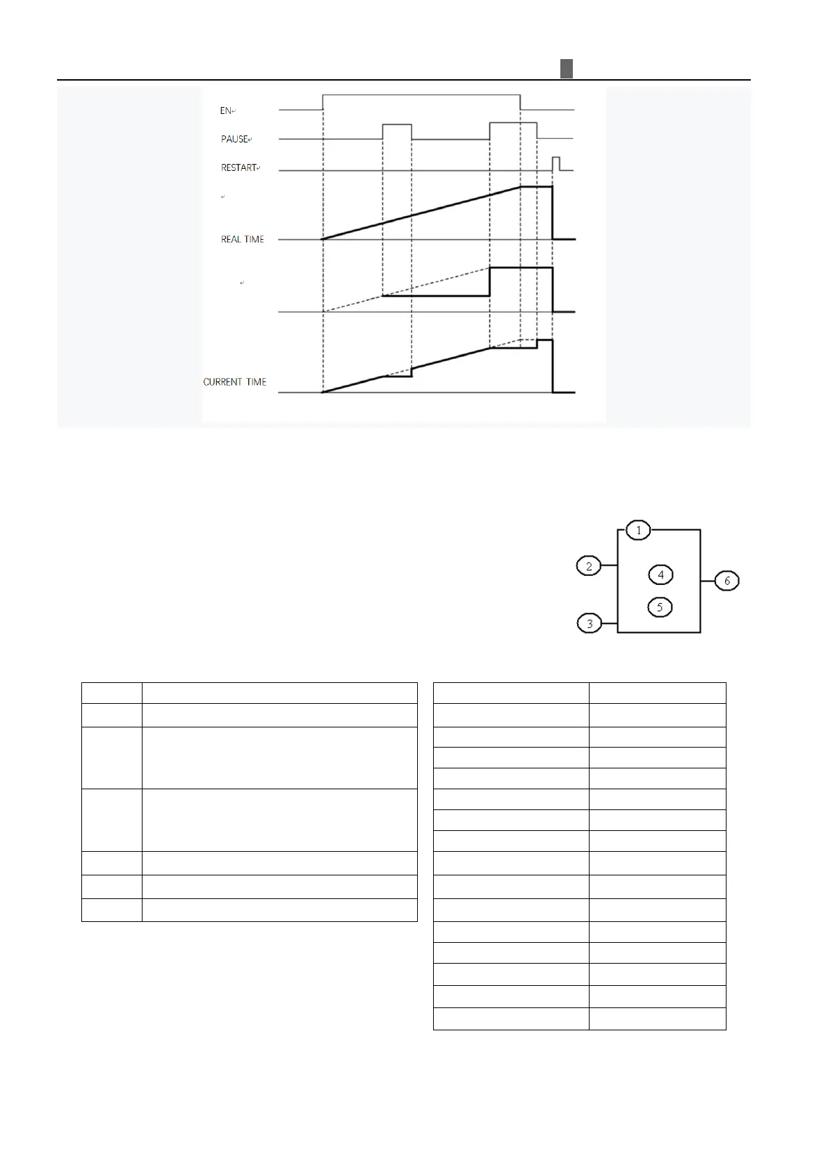
6BCounter Instructions
The iSmart includes 31 counters that can be used throughout a program. Each
counter has a choice of 9 operation modes, 1 for pulse counter, 6 for general
purpose counting and 2 for high speed counting. Additionally, each counter has 6
parameters for proper configuration. The tables below describe each configuration
parameter and lists each compatible memory type for configuring counters.
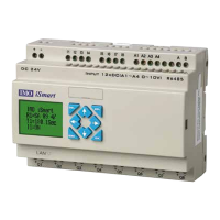
Common Counter
①
②
Use (I01~g1F) to set counting up or down
OFF: counting up (0, 1, 2, 3……)
ON: counting down (……3, 2, 1, 0)
③
Use (I01~g1F) to reset the counting value
ON: the counter value reset to 0
OFF: the counter continues to count
④
Counter current Value, range: 0~999999
⑤
Counter preset Value, range: 0~999999
⑥
Counter Code (C01~C1F total: 31 Counters)
※ The preset value of Counter could be a constant or other function current value.