Do you have a question about the IMO iSmart V4 and is the answer not in the manual?
UK office details for IMO Precision Controls, providing industrial automation solutions.
Italian office contact information for IMO Automazione, specializing in industrial automation.
Contact details for IMO Canada, offering industrial automation and control products.
A compilation of contact information for various IMO group offices globally.
A simple guide to connecting, programming, and operating the iSmart relay for initial use.
Step-by-step instructions to set up communication between a PC and the iSmart relay.
A basic tutorial on creating and implementing a simple program on the iSmart relay.
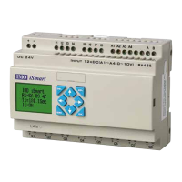
Technical specifications of the iSmart relay, including power, programming, and environmental data.
Guidelines for correctly installing the iSmart relay using DIN-rail or direct mounting methods.
Detailed instructions and diagrams for wiring the iSmart relay's inputs and outputs.
Comprehensive guide to using the Ladder Logic environment for programming the iSmart relay.
Explanation of the simulation mode for testing and debugging programs before deployment.
Process for transferring the developed program from the PC to the iSmart relay.
Fundamental symbols and elements used in Relay Ladder Logic programming for iSmart.
Details on using virtual auxiliary coils (M) for internal logic and control within the iSmart relay.
Details on Counter coils, their modes, configuration, and compatible memory types.
Explanation of Set, Reset, and Pulse output instructions for controlling device outputs.
Overview of various function blocks available in FBD mode for advanced programming.
Configuration and usage of the PID function block for control applications.
Implementing Modbus communication using the MU function block for data exchange.
Detailed specifications for different iSmart models, covering I/O, HMI, and communication features.
Technical data for various input types, including digital, analog, and high-speed inputs.
Information on relay and transistor outputs, including load ratings, response times, and wiring notices.
Setting up RS485 communication parameters for iSmart devices.
Using the MU instruction for Modbus RTU master communication with iSmart devices.
Configuring the iSmart unit to act as a Modbus RTU slave for data control.
Overview of iSmart expansion modules, including digital, analog, and communication types.
Instructions for setting up and configuring digital IO expansion modules.
Details on the 2-channel analog output module, its modes, and wiring connections.
Guidance on using SD cards for data transfer, program storage, and configuration.
Procedures for managing programs on SD cards using iSmart keypad or PC client.
How to set device configuration parameters using .ini files on an SD card.
Configuring network settings like IP address, subnet mask, and master/slave mode.
Establishing a connection between the iSmart controller and a PC via Ethernet using SMT Client.
Setting up network I/O for communication and data exchange between iSmart units.