Chapter 5 Relay Ladder Logic Programming 121
-
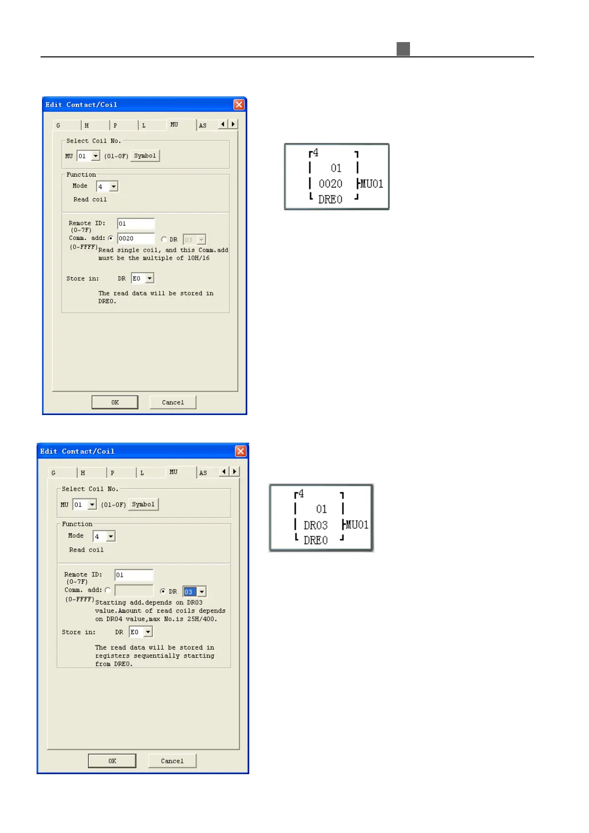
MU mode4: Read Coils
S
et parameter ③, address, to be constant:
F
unction parameter display:
Set
a constant address 20 ( here is a Hex number)
Data length is a constant value: 10 in Hex format
When enable the MU function, the sending out Modbus
command will be:
01 01 00 20 00 10
CRC16;
Received response from slave:
01 01 02 data1-1 data1-2 CRC16;
Saving data to DRE0:
D
RE0 = data1-1 + data1-2
S
et parameter ③, address, refer to data register DR:
F
unction parameter display:
S
et DR03=0001 for address
Set DR04=0015 (hex: 000F) for data length;
(means how many coil’s state will be read)
When enable the MU function, the sending out Modbus
command will be:
01 01 00 01 00 0F CRC16;
Received response from slave:
01 01 02 data1-1 data1-2 CRC16;
Saving data to DRE0:
DRE0 = data1-1 + data1-2
※
the max length of data is 400.
 Loading...