Chapter 5 Relay Ladder Logic Programming 123
-
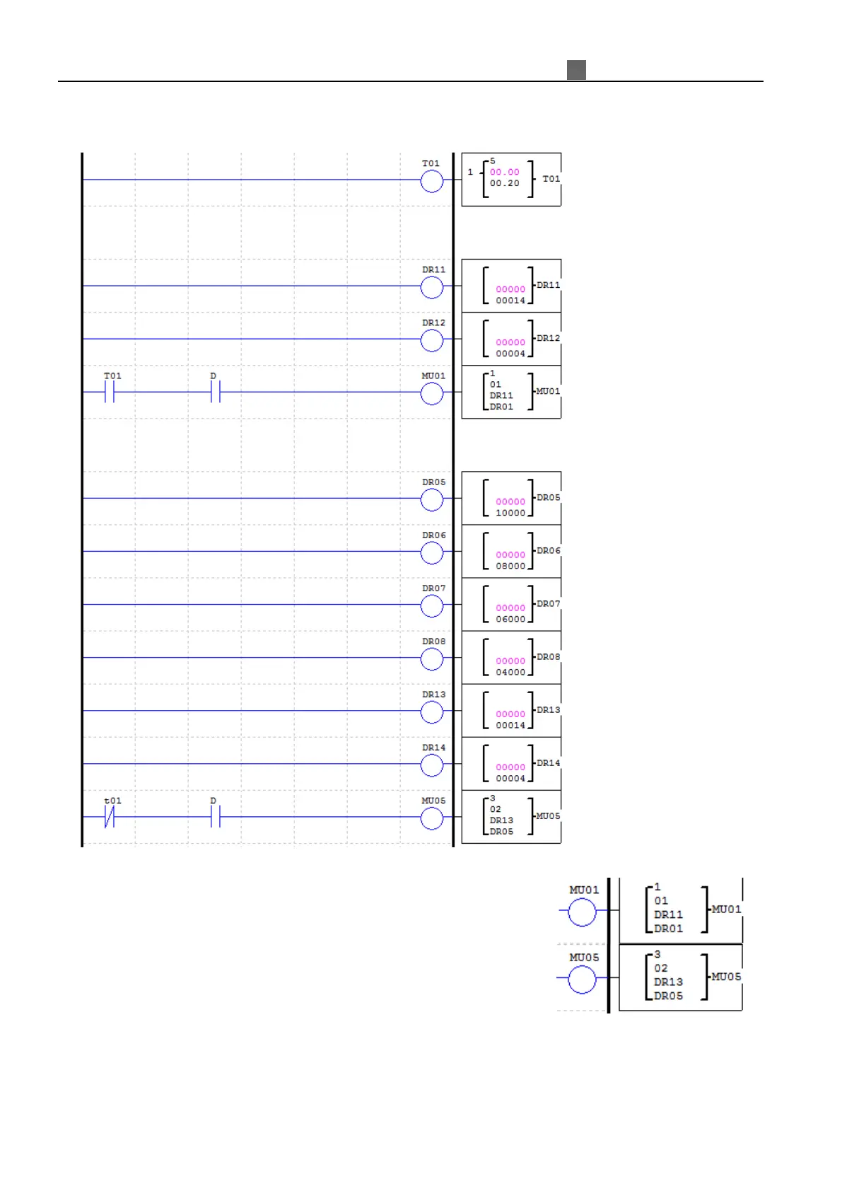
Example:
MU sending and receiving data via RS485 port when it is enabled. Here recommends user to put the D-trigger
element in front of the MU coil.
M
U01 and MU05 coils are controlled by T01 as shown in above figure. Set
MU01 as mode1, read registers mode, address starts from DR11=14=0x0E, data
length DR12=4, and saving data to the registers from DR01 to DR04.
Setting MU05 as mode3, write multiple registers mode, address
DR13=14=0x0E, data length DR14=4, and the data which want to write into
target registers refer to the value of the register, from DR05 to DR08
(DR05=10000=0x2710, DR06=8000=0x1F40, DR07=6000=0x1770,
DR08=4000=0x0FA0);
When T01 turns ON, MU01 is going to be triggered to send command 01 03 00 0E 00 04 CRC16, then saving
the received data to DR01~DR04. After 0.2s T01 OFF, then trigger MU05 sending command 01 10 00 0E 00 04 08
27 10 1F 40 17 70 0F A0 CRC16, writing 4 sets data to the registers (0x0E~0x11) in the slave.