EasyManua.ls Logo

IMO iSmart V4 - Page 155

IMO iSmart V4
274 pages
Print Icon
To Next Page IconTo Next Page
To Previous Page IconTo Previous Page
Loading...
Chapter 6 FBD Block Diagram Programming 135
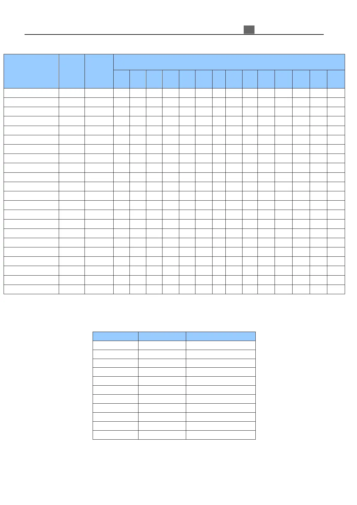
Each function block occupied a BLOCK; the available number is limited by the number of B, system memory
space and function block number.
Block
number
System
memory
(byte)
Function Block number
T C R G AS MD PI MX AR DR MU F
NA
I
NA
Q
Total source
500
10000
250
250
250
250
250
250
30
250
30
240
250
250
250
250
Timer mode 0
1
5
1
Timer mode1~6
1
10
1
Timer mode 7
1
12
2
Counter mode 0
1
5
1
Counter mode 1~7
1
14
1
Counter mode 8
1
16
1
RTC mode 0
1
5
1
RTC mode 1~4
1
11
1
Analog mode 0
1
5
1
Analog mode 1~7
1
12
1
AS
1
11
1
MD
1
11
1
PID
1
17
1
MX
1
17
1
AR
1
23
1
DR
1
6
1
MU
1
12
1
Filter mode0
1
5
1
Filter1~4
1
10
1
NAI
1
1
NAQ
1
1
Logic Block include AND, AND EDGE, NAND, NAND EDGE, OR, NOR XOR, NOT, RS, PULSE, BOOLEAN.
Each logic block occupied a BLOCK; the available number is limited by the number of B and system memory space.
Logic function blocks source show as blow table:
Logic
Block number
System memory (byte)
AND
1
8
AND(EDGE)
1
8
NAND
1
8
NAND(EDGE)
1
8
OR
1
8
NOR
1
8
XOR
1
6
RS
1
6
NOT
1
4
PULSE
1
4
BOOLEAN
1
12

Table of Contents