Chapter 6 FBD Block Diagram Programming 142
Example:
The state of N01, N02 and N03 are 000, so PWM output pulse is stage1 like this as setting above:
The state of N01, N02 and N03 decide PWM output. PWM stages can be changed by the status of N01, N02 and N03
when P01 is running.
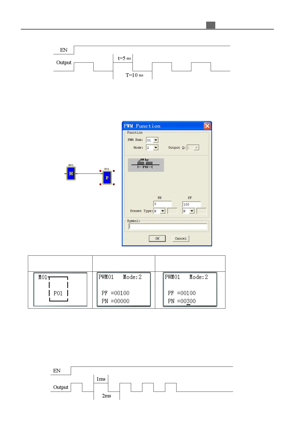
Mode2 PLSY
The PLSY output terminal Q01 can output preset number of pulse whose frequency is variable from 1 to 1000 Hz.
M01: enable input coil
function display
“OK” to edit preset value
※ PF: Preset frequency of PLSY (1~1000Hz); PN: Preset pulse number of PLSY (0~32767);
※ Total number of pulses storing in DRC9;
※ PLSY stops outputting pulse after it has output PN pulses.
※ PLSY will be going on as long as it is enabled if PN is 0.
Example:
Parameter setting: PF= 500Hz, PN = 5, output as shown below:
PLSY stops outputting when the number of output pulse is completed.