IS620P User Manual Chapter 6 Troubleshooting
- 113 -
The procedure of removing the cause of positioning inaccurate is as follows:
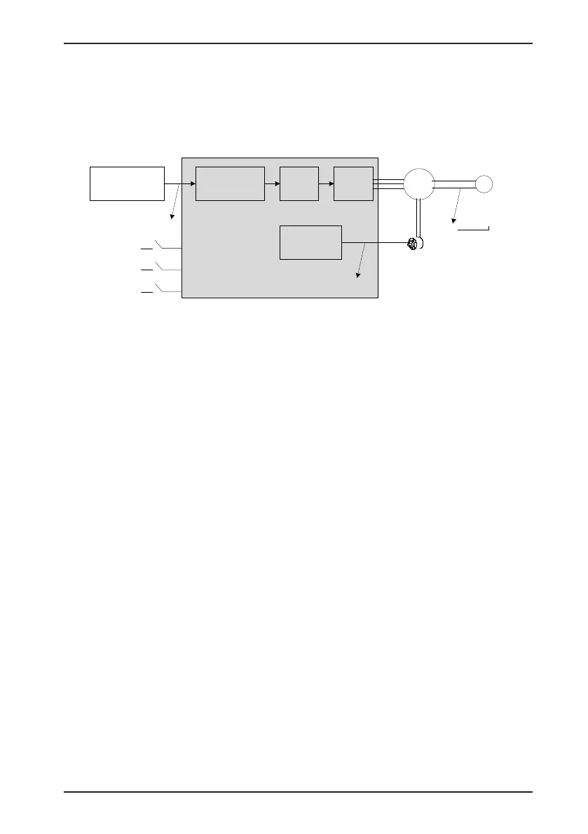
The following gure shows the positioning control schematic diagram.
Figure 6-1 Positioning control schematic diagram
Electronic
gear ratio
Servo
motor
Encoder
Machine
Servo
control
Feedback pulse
counter
Pf: H0B-17
(3)
Input reference
pulse counter
Pin: H0B-13
(2)
A
B
C
Servo enabled signal
S-ON
Count value of output
position references
Pout
(1)
Position reference
output device
Servo drive
Mechanical stop
position PL
(4)
Forward/Reverse
overtravel switch
P-OT/ N-OT
Position error
clearing signal
When positioning is inaccurate, check the four signals in Figure 6-1.
1. Count value of output position references Pout of the position reference output device
(host computer or internal parameters of the drive)
2. The input reference pulse counter Pin received by the servo drive, corresponding to H0B-
13
3. The accumulative feedback pulses from the encoder, corresponding to H0B-17
4. Mechanical stop position PL
There are three causes resulting in inaccurate positioning, corresponding to A, B and C in
Figure 6-1.
A: The counting of input position reference is incorrect because the cable connecting the
position reference output device (host computer) and the servo drive is affected by noise.
B: The input position reference is interrupted during the motor running. This is because, the
servo enabled signal (S-ON) is set to OFF, the forward/reverse overtravel switch signal (P-OT
or N-OT) is ON and the position deviation clearing signal (ClrPosErr) is ON.
C: Mechanical position slides between the machine and the servo motor.
In the prerequisite of no occurrence of position deviation, the following relationships exist.
•
Pout = Pin, count value of output position references = Input position reference counter
•
Pin x electronic gear ratio = Pf, Input position reference counter x electronic gear ratio =
accumulative feedback pulses
•
Pf x
△
L = PL, accumulative feedback pulses x corresponding load displacement of one
position reference = mechanical stop position

 Loading...
