IS620P User Manual Chapter 3 Wiring of Servo System
- 67 -
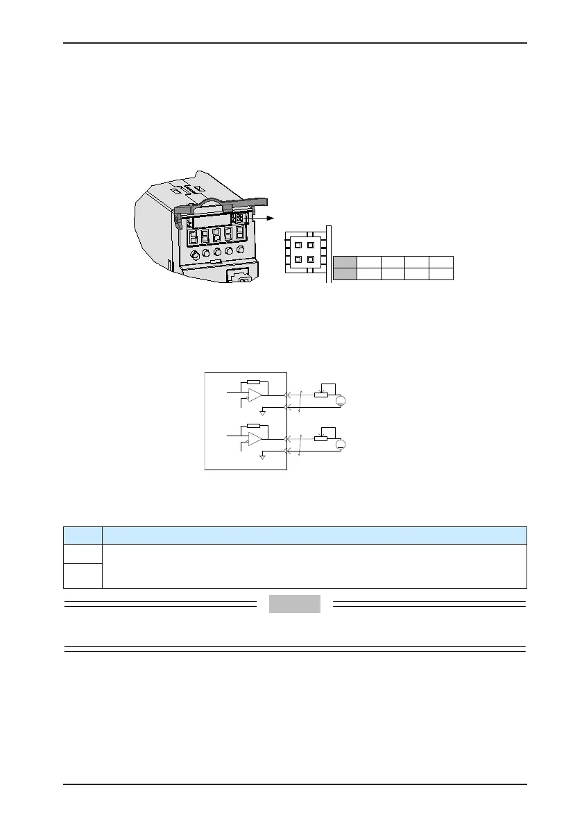
3.5 Analog Monitoring Signal Wiring
The following gures shows pin layout of the analog monitoring signal terminal CN5.
Figure 3-16 Analog monitoring signal terminal
No.
Signal
1
GND
2
AO1
3
GND
4
AO2
Corresponding interface circuit:
•
Analog output: -10 to +10 V
•
Maximum output current: 1 mA
Servo drive
GND
AO1
A
GND
AO2
A
Single-direction
1mA
GALV
Single-direction
1mA
GALV
2
3
4
3
The monitored objects of analog signals are listed in the following table.
Table 3-24 Monitored objects of analog signals
Signal Monitored Object
AO1 0: Motor speed, 1: Speed reference, 2: Torque reference, 3: Position deviation, 4: Position
amplier deviation, 5: Position reference speed, 6: Positioning completed reference, 7:
Speed feedforward (H04-50/H04-53)
AO2
After the control power turns OFF, the analog monitoring output terminal may output around 5 V
voltage for 50 ms at most. Take this into full consideration when using this terminal.

 Loading...
