Chapter 3 Wiring of Servo System IS620P User Manual
- 56 -
Make sure "2.8 V ≤ (H level) - (L level) ≤ 3.7 V". Otherwise, input pulses of the servo drive are
unstable, which will cause:
•
When the reference pulse is input, pulse loss occurs.
•
When the reference direction is input, the direction will reverse.
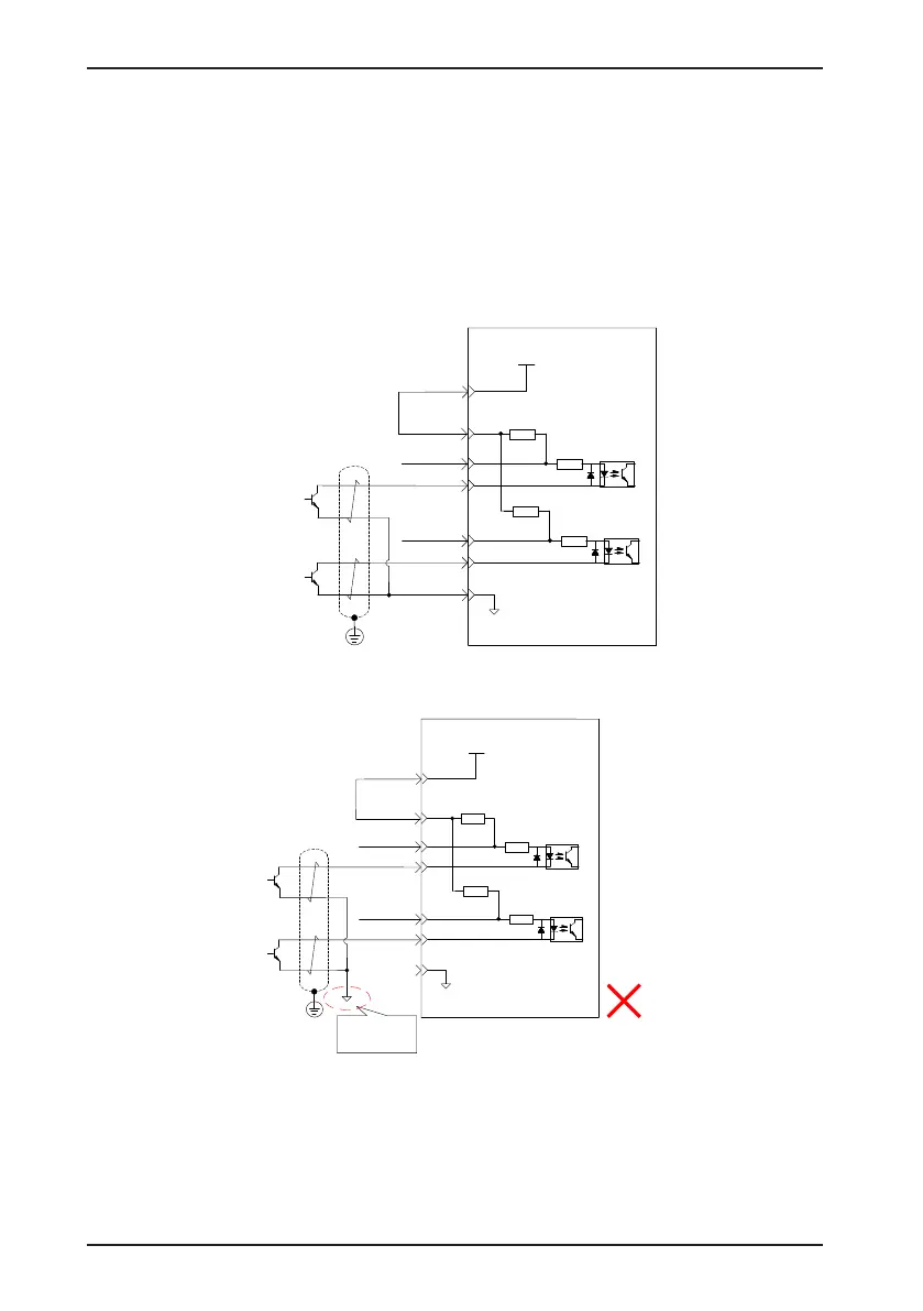
b) OC mode
When the internal 24 V power supply of the servo drive is used:
Servo drive
PULSE+
PULSE-
35
41
43
240 Ω
PULLHI
SIGN+
SIGN-
37
39
240 Ω
2.4 kΩ
2.4 kΩ
+24 V power supply
24V
17
COM-
14
OC pulse position reference
Min. pulse width:
Max. input frequency:
200
2.5 us
kpps
Wrong connection: Pin 14 (COM-) is not connected, which cannot form a closed-loop circuit.
Servo drive
PULSE+
PULSE-
35
41
43
240 Ω
PULLHI
SIGN+
SIGN-
37
39
240 Ω
2.4 kΩ
2.4 kΩ
+24 V power supply
24V
17
COM-
14
Pin 14 (COM-)
not connected

 Loading...
