Chapter 3 Wiring of Servo System IS620P User Manual
- 62 -
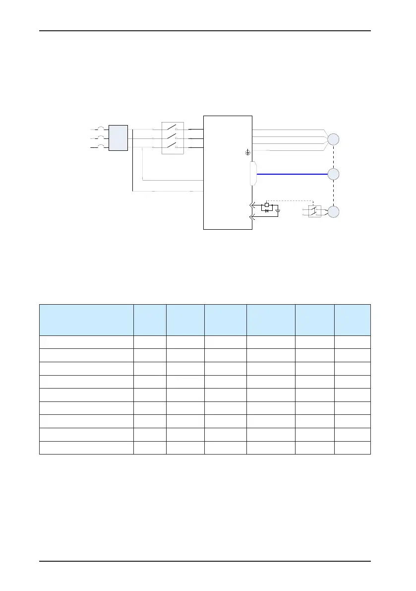
1) Wiring example of holding brake
The connector of the holding brake is of no polarity. You needs to prepare a 24 V external
power supply. The following gure shows the standard wiring of brake signal (/BK) and power
supply of the brake.
Figure 3-10 Wiring of the holding brake
Brake control relay
Servo drive
CN1
BK-RY
+24V
DO5+(/BK+)
DO5-(/BK-)
+24V
(Brake power supply)
Encoder
Brake
Motor
EMI
filter
L1C
L2C
Three-phase
220/380 VAC
R
S
T
U
V
W
M
CN2
PG
BK
2) Wiring precautions
a. To decide the length of the cable on the motor brake side, consider voltage drop caused
by the cable resistance. The input voltage must be at least 21.6 V to make the brake
work. The following table lists brake specications of ISMH servo motors.
Table 3-18 Brake specications
Servo Motor Model
Holding
Torque
(N·m)
Supplied
Voltage
(V)±10%
Resistance
(Ω) ±7%
Supplied
Current
Range (A)
Release
Time (ms)
Applying
Time
(ms)
ISMH1-10B 0.32 24 96 0.23–0.27 10 30
ISMH1-20B/40B 1.3 24 82.3 0.25–0.34 20 50
ISMH1-75B 2.39 24 50.1 0.40–0.57 25 60
ISMH2-10C/15C/20C/25C 8 24 25 0.81–1.14 30 90
ISMH2-30C/40C/50C 16 24 21.3 0.95–1.33 60 120
ISMH3-85B/13C/18C 16 24 21.3 0.95–1.33 60 120
ISMH3-29C/ 44C/55C/75C 48 24 13.7 1.47–2.07 100 230
ISMH4-40B 1.3 24 82.3 0.25–0.34 20 50
ISMH4-75B 2.39 24 50.1 0.40–0.57 25 60
b. The brake shall not share the same power supply with other devices. Otherwise, the
brake may conduct false operation due to voltage or current drop resulted from working of
other devices.
c. Cables of 0.5 mm
2
and above are recommended.

 Loading...
